Heat dissipation device having phase-changeable medium therein

a technology of heat dissipation device and phase-changeable medium, which is applied in the direction of insulated conductors, lighting and heating apparatus, cables, etc., can solve the problems of air gaps, face cannot have intimate contact, and the stability of the operation of electronic devices will be severely affected

Inactive Publication Date: 2007-09-11
FU ZHUN PRECISION IND SHENZHEN +1
View PDF9 Cites 42 Cited by
  • Summary
  • Abstract
  • Description
  • Claims
  • Application Information

AI Technical Summary

Problems solved by technology

If the heat is not dissipated duly, the stability of the operation of the electronic devices will be impacted severely.
However, the column and the core have a certain degree of roughness at the outer face of column and the inner face of the core; thus, the two faces can not have an intimate contact with each other, and air gaps exist between the two faces.
Therefore, a high thermal resistance exists between the column and the core of the heat dissipation body, which results in a low heat transferring efficiency between the two faces.
Consequently, the heat generated by the electronic device cannot timely reach the fins to be dissipated.
The normal function of the electronic device is impacted adversely.

Method used


Image

  • Heat dissipation device having phase-changeable medium therein
  • Heat dissipation device having phase-changeable medium therein
  • Heat dissipation device having phase-changeable medium therein

Examples


Embodiment Construction

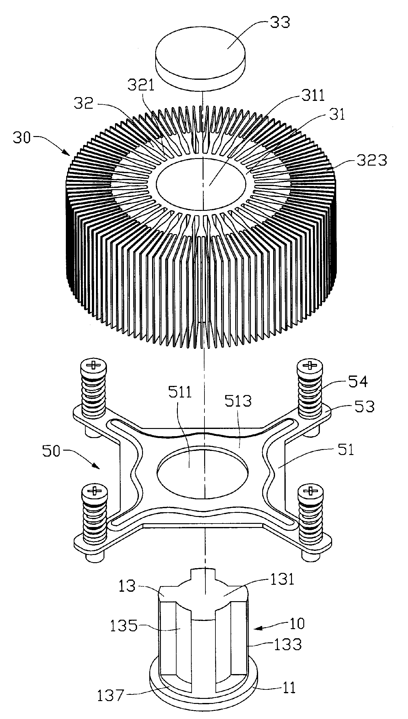
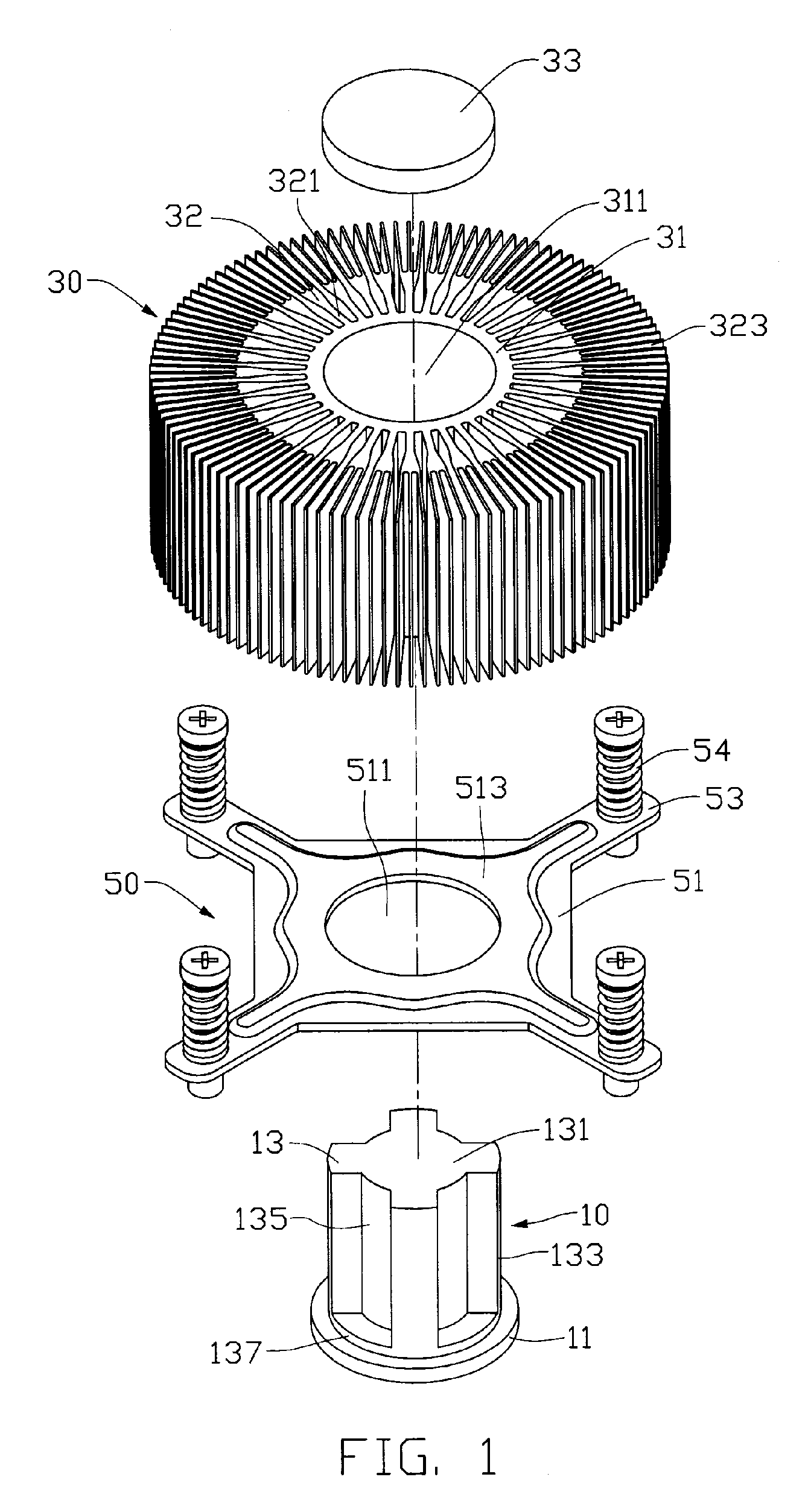
[0011]Referring to FIG. 1, a heat dissipation device in accordance with a preferred embodiment of the present invention comprises a heat sink and a locking device 50 for securing the heat sink to a heat generating electronic device (not shown) located on a printed circuit board (not shown). The heat sink comprises a heat conducting body 10 and a heat dissipation body 30 thermally engaged with the conducting body 10.

[0012]The heat conducting body 10, which is made of metal having a good heat conductivity such as copper, comprises a circular heat receiver 11 and a column 13 extending upwardly from the heat receiver 11. The column 13 comprises a solid core 131 in a center thereof. Four uniformly distributing spokes 133 extend radially from a periphery of the core 131. Four notches 135 are defined between the spokes 133 and the core 131. The column 13 has a round bottom portion 137 below the notches 135 and above the heat receiver 11.

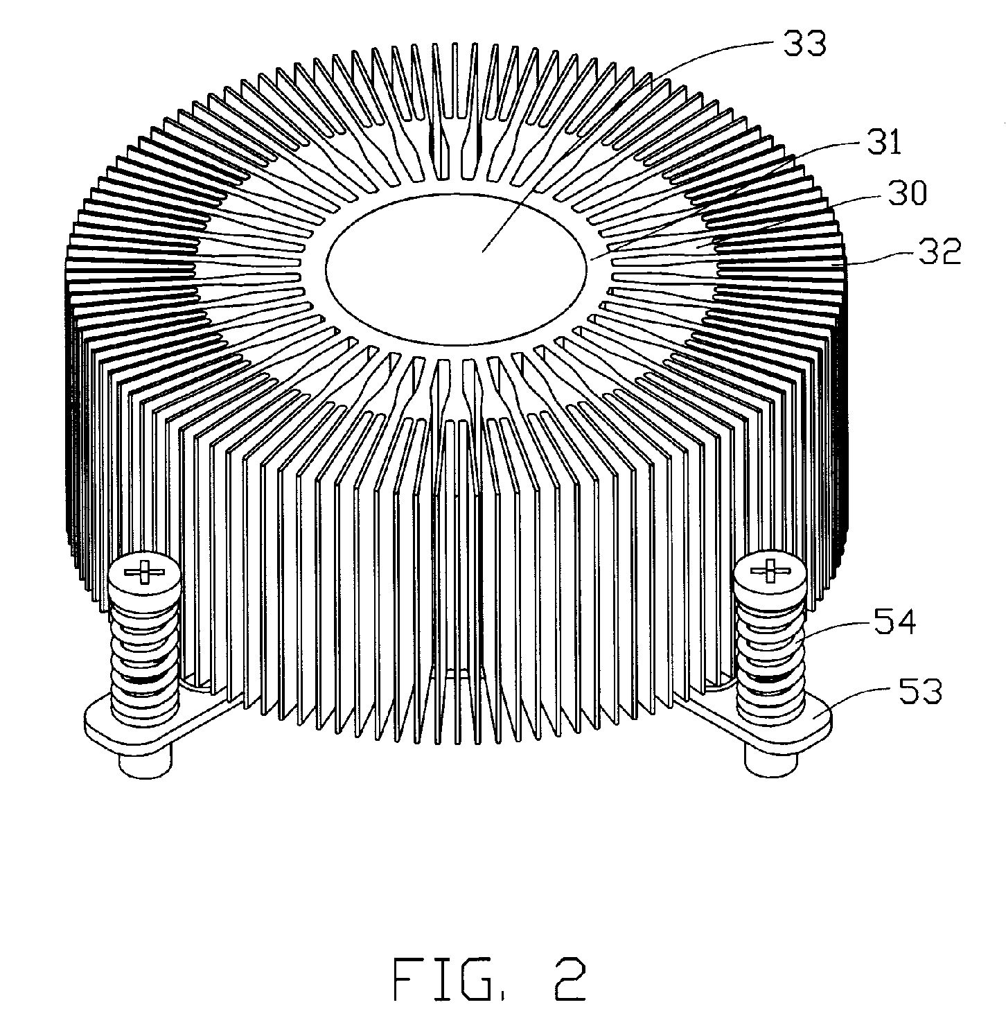
[0013]The heat dissipation body 30 comprises a cylind...


PUM


Abstract

A heat dissipation device includes a heat dissipation body and a heat conducting body thermally combined with the heat dissipation device. The heat dissipation body includes a central portion defining a through hole therein and a plurality of fin extending from a periphery of the central portion. Each of the fins branches a plurality of portions at an end thereof. The heat conducting body includes a column thermally fitted in the through hole of the central portion of the heat dissipation body. A cavity is defined between the column and the central portion of the heat dissipation body. The cavity contains a phase-changeable medium therein, which becomes vapor once the column absorbs heat from a heat-generating electronic device.

Description

FIELD OF THE INVENTION[0001]The present invention relates generally to a heat dissipation device, and more particularly to a heat dissipation device used for dissipating heat generated by an electronic device.DESCRIPTION OF RELATED ART[0002]With advancement of computer technology, electronic devices operate rapidly. It is well known that more rapidly the electronic devices operate, more heat they generate. If the heat is not dissipated duly, the stability of the operation of the electronic devices will be impacted severely. Generally, in order to ensure the electronic device to run normally, a heat dissipation device is used to dissipate the heat generated by the electronic device.[0003]Conventionally, the heat dissipation device has a heat sink. The heat sink comprises a heat conducting column and a cylindrical heat dissipation body. The cylindrical heat dissipation body comprises a cylindrical core and a plurality of fins extending radially outwards from the core. The core defines...

Claims


Application Information

Patent Timeline
Patent Type & Authority Patents(United States)
IPC IPC(8): H05K7/20
CPCH01L23/4006H01L23/427H01L23/467F28F2215/10H01L2924/0002H01L2924/00
Inventor CHEN, CHUN-CHIZHOU, SHI-WENWU, ZHAN
Owner FU ZHUN PRECISION IND SHENZHEN
Why Eureka
Try Eureka