Vehicular lamp

a technology of vehicular lamps and lampshades, which is applied in the field of vehicular lamps, can solve the problems of unattractive appearance of the lamp in its lit-up state, inability to efficiently achieve light distribution control of vehicular lamps with high precision, and achieve the effect of attractive appearance and enhanced luminous flux utilization factor of light from the light-emitting elemen

Active Publication Date: 2007-09-18
KOITO MFG CO LTD
View PDF11 Cites 100 Cited by
  • Summary
  • Abstract
  • Description
  • Claims
  • Application Information

AI Technical Summary

Benefits of technology

[0010]The present invention is to solve the above-described problems, and it is an object of the present invention to provide a vehicular lamp that uses a light-emitting element as a light source in which the lamp has a more attractive appearance in its lit-up state, the light distribution control can be done with high-precision, and the luminous flux utilization factor for light from the light-emitting element is enhanced.
[0011]The present invention accomplishes the above object by a structure in which the translucent member is disposed to cover the light-emitting element from its front side and the peripheral region of the translucent member has an innovative construction.

Problems solved by technology

The use of the translucent member in Japanese Patent Application Laid-Open (Kokai) No. 2000-67610 enables enhancement of the luminous flux utilization factor for the light from the light-emitting element but causes some problems.
One problem is that since the peripheral region of the translucent member is constructed as the mortar-shaped light guiding body, only the leading end portion of the peripheral region looks bright when the translucent member is observed from an area in front of the lamp.
This causes another problem of unattractive appearance of the lamp in its lit-up state.
The further problem resulting from this fact is that light distribution control of the vehicular lamp with high precision cannot be made efficiently.

Method used


Image

  • Vehicular lamp
  • Vehicular lamp
  • Vehicular lamp

Examples


first embodiment

[0047]the present invention will be described first.

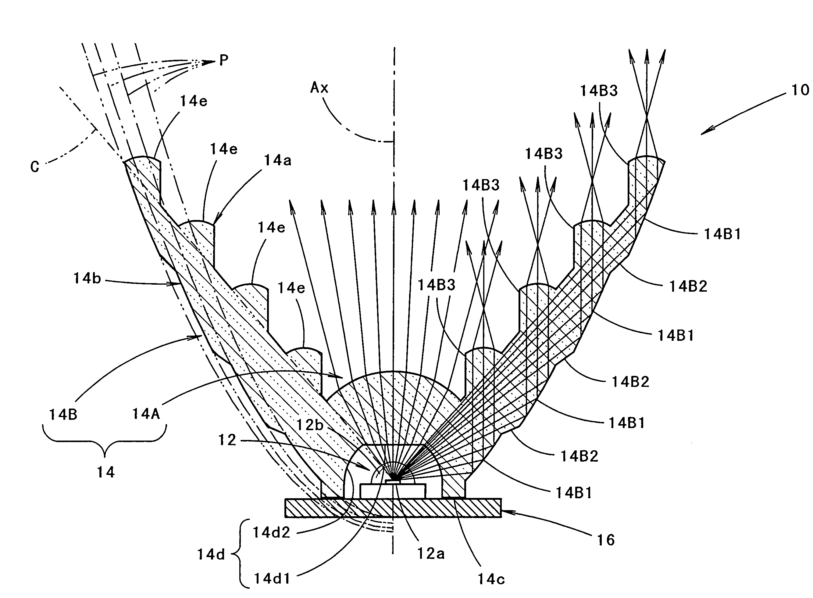
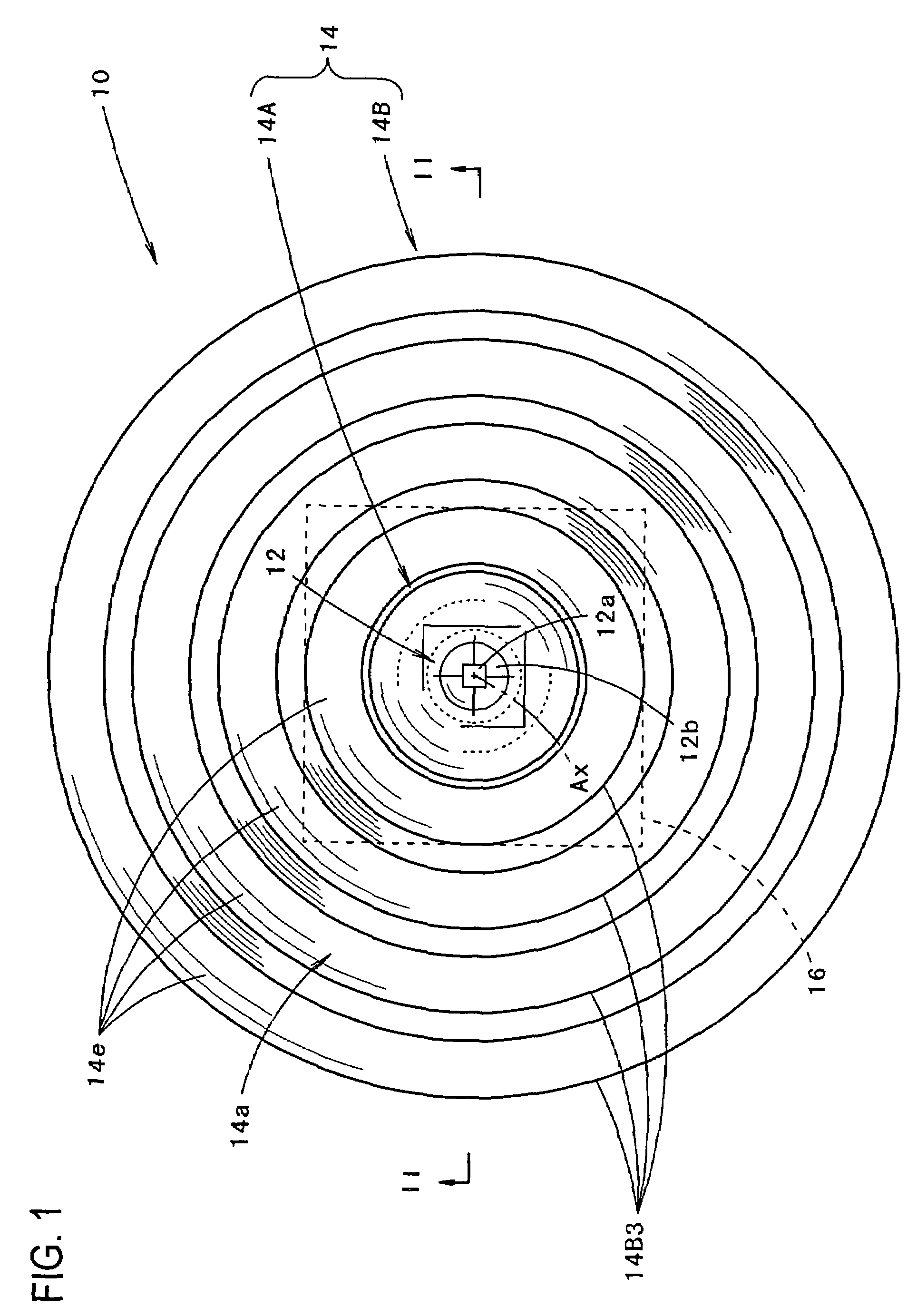
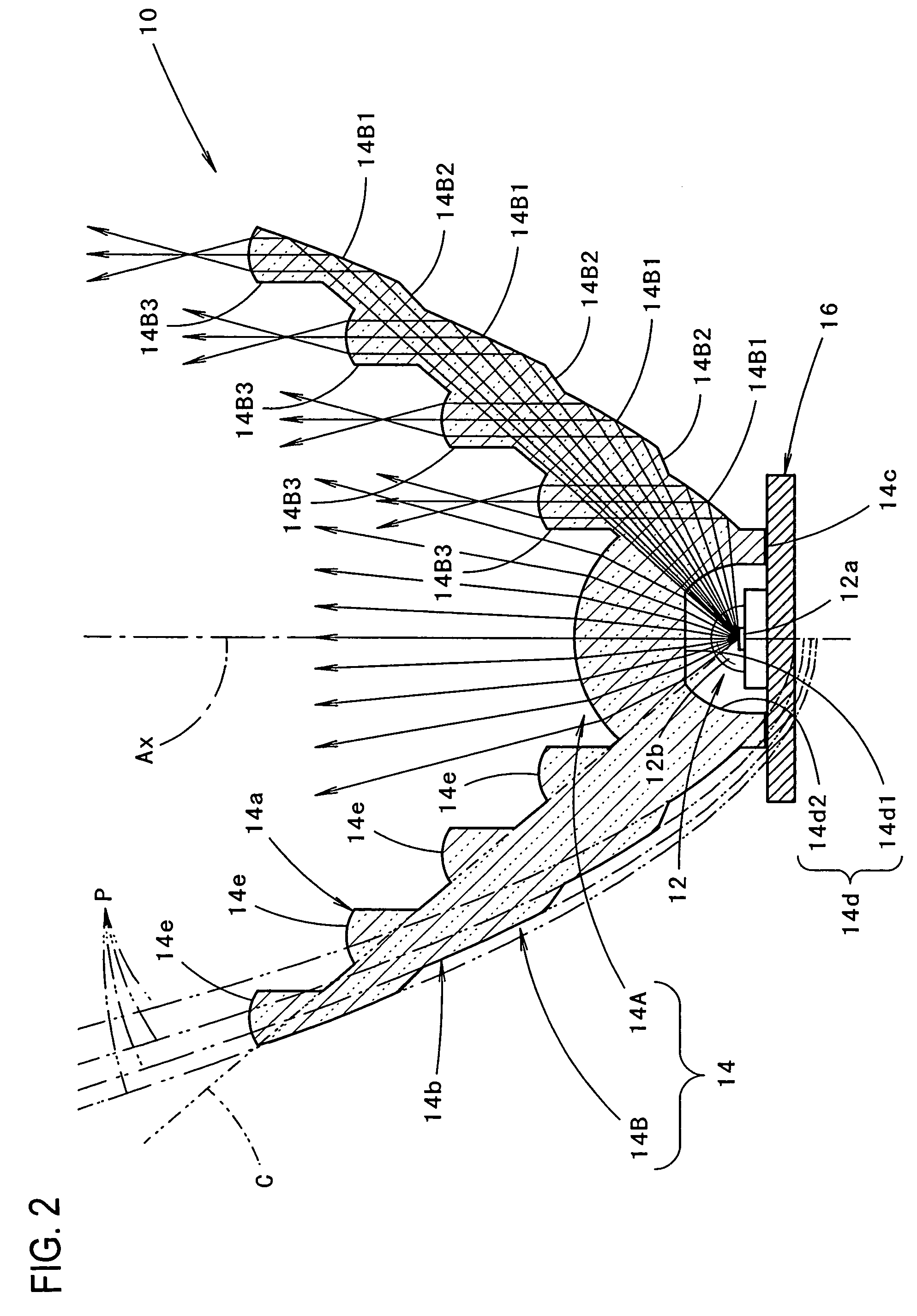
[0048]FIG. 1 shows the vehicular lamp according to the first embodiment of the present invention, and FIG. 2 shows the lamp in cross-section along the line II-II in FIG. 1.

[0049]As shown in FIGS. 1 and 2, the vehicular lamp 10 of the first embodiment of the present invention is a taillight mounted at the rear end portion of a vehicle. The vehicular lamp 10 is provided with a light-emitting element 12 and a translucent member 14 and has an optical axis Ax that extends in the longitudinal direction of the vehicle.

[0050]The light-emitting element 12 is a red light-emitting diode that consists of a light-emitting chip 12a and a sealing resin 12b. The light-emitting chip 12a, which is about 0.3 to 1 mm squares, is covered with the sealing resin 12b in a hemispherical manner. With the light-emitting chip 12a directed forward with respect to the vehicular lamp (“backward” with respect to the vehicle, as is true in the following) on the op...

second embodiment

[0078]Next the present invention will be described.

[0079]FIG. 4 is a front view the vehicular lamp 110 according to the second embodiment of the present invention.

[0080]As seen from FIG. 4, as far as the basic constructions of the light-emitting element parking meter machine and the translucent member 14 are concerned, the vehicular lamp 110 is the same as the above-described first embodiment. However, the construction of the reflected light control portion 14B of the translucent member 14 of the second embodiment is partially different from that of the first embodiment.

[0081]More specifically, in the second embodiment of the present invention, the front end face 14e of each of the ring-shaped protruding portions 14B3 of the reflected light control portion 14B is circumferentially divided into a plurality of sectors 14e1, and the surface of each of these sectors 14e1 has a convex spherical shape.

[0082]FIG. 5 is a front view of the vehicular lamp 110 according to the second embodimen...

third embodiment

[0086]Next the present invention will be described.

[0087]FIG. 6 is a front view of the vehicular lamp 210 according to the second embodiment of the present invention, and FIG. 7 shows the lamp 210 in cross-section along the line VII-VII in FIG. 6.

[0088]As seen from FIGS. 6 and 7, the vehicular lamp 210 is a taillight mounted on the right side in the rear end portion of the vehicle. The vehicular lamp 210 is constructed so that nine pairs of light-emitting elements 12 and translucent members 14 are accommodated according to a two-stage vertical arrangement in the lamp chamber that is formed by a lamp body 22 and a plain translucent cover 24 attached to the front end opening of the lamp body 22. In this third embodiment as well, the respective pairs of light-emitting elements 12 and translucent members 14 are completely identical in construction with those of the first embodiment.

[0089]In the third embodiment of the present invention, the translucent members 14 are integrated to form ...


PUM


Abstract

A vehicular lamp in which a luminous flux utilization factor is enhanced by a structure of a light-emitting element that is disposed to face forward with respect to a vehicular lamp and covered from its front side with a translucent member. The circumferential region of the translucent member forms a reflected light control portion that allows light from the light-emitting element which has impinged on the translucent member to be internally reflected by the rear face of the translucent member and turned into parallel light which travels forward, and the reflected light control portion further allows the parallel light to emit forward from the front face of the reflected light control portion.

Description

BACKGROUND OF THE INVENTION[0001]1. Field of the Invention[0002]The present invention relates to a vehicular lamp that uses a light-emitting element as a light source.[0003]2. Prior Art[0004]Recent years have seen adoption of many vehicular lamps having a light-emitting element serving as the light source.[0005]Japanese Patent Application Laid-Open (Kokai) No. 2000-67610 discloses a vehicular lamp including a light-emitting element disposed to face forward on an optical axis extending in the longitudinal direction of the lamp and a translucent member disposed to cover the light-emitting element from its front side.[0006]In this vehicular lamp, a central region of the translucent member which is located close to the optical axis is constructed so as to allow light from the light-emitting element, which has impinged on the translucent member, to emit forward from its front face. Further, the peripheral region of the translucent member which is located around the central region is cons...

Claims


Application Information

Patent Timeline
Patent Type & Authority Patents(United States)
IPC IPC(8): F21V5/00F21S8/10F21V5/04F21V7/00F21Y101/00G01D11/28
CPCF21V5/04F21V7/0091F21Y2115/10F21S43/14F21S43/26F21S43/315
Inventor AMANO, YASUYUKI
Owner KOITO MFG CO LTD
Why Eureka
Try Eureka