
Process and system for controlling an electronic power component and data recording support comprising instructions for executing the process

a technology of electronic power components and process, applied in the direction of process and machine control, pulse technique, instruments, etc., can solve the problem of inability to block the process piloting each opening and/or closing, and achieve the effect of avoiding unnecessary energy consumption or deterioration of the electronic power componen

Active Publication Date: 2007-09-18
ALSTOM TRANSPORT TECH SAS
View PDF9 Cites 1 Cited by
  • Summary
  • Abstract
  • Description
  • Claims
  • Application Information

AI Technical Summary

Benefits of technology

The invention is a control process for an electronic power component that includes a piloting process for opening and closing the component. The process is controlled by a computer that reads the value of operational parameters, such as voltage and current, and uses those readings to determine if the component is responding to the application of commutation voltages in a timely manner. If the response is satisfactory, the process continues normally. If there is a problem with the component, the process is interrupted and a safeguarding process is initiated to prevent damage to the component. The control process ensures that the reaction time of the component is monitored and that the process is always advancing. This prevents unnecessary energy consumption and avoids deterioration of the component. The control process is adaptable to different electronic power components and can be recorded for future reference.

Problems solved by technology

Consequently, in such a control process, it is impossible that the process piloting each opening and / or closure remains blocked.

Method used


Image

  • Process and system for controlling an electronic power component and data recording support comprising instructions for executing the process
  • Process and system for controlling an electronic power component and data recording support comprising instructions for executing the process
  • Process and system for controlling an electronic power component and data recording support comprising instructions for executing the process

Examples


Embodiment Construction

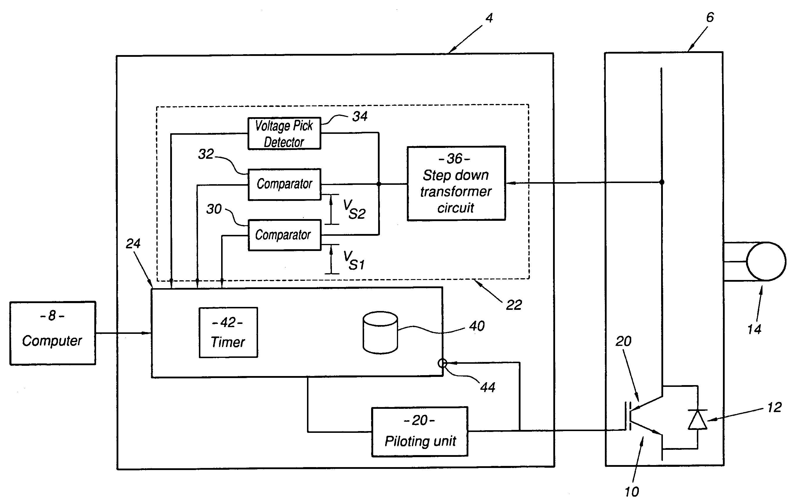
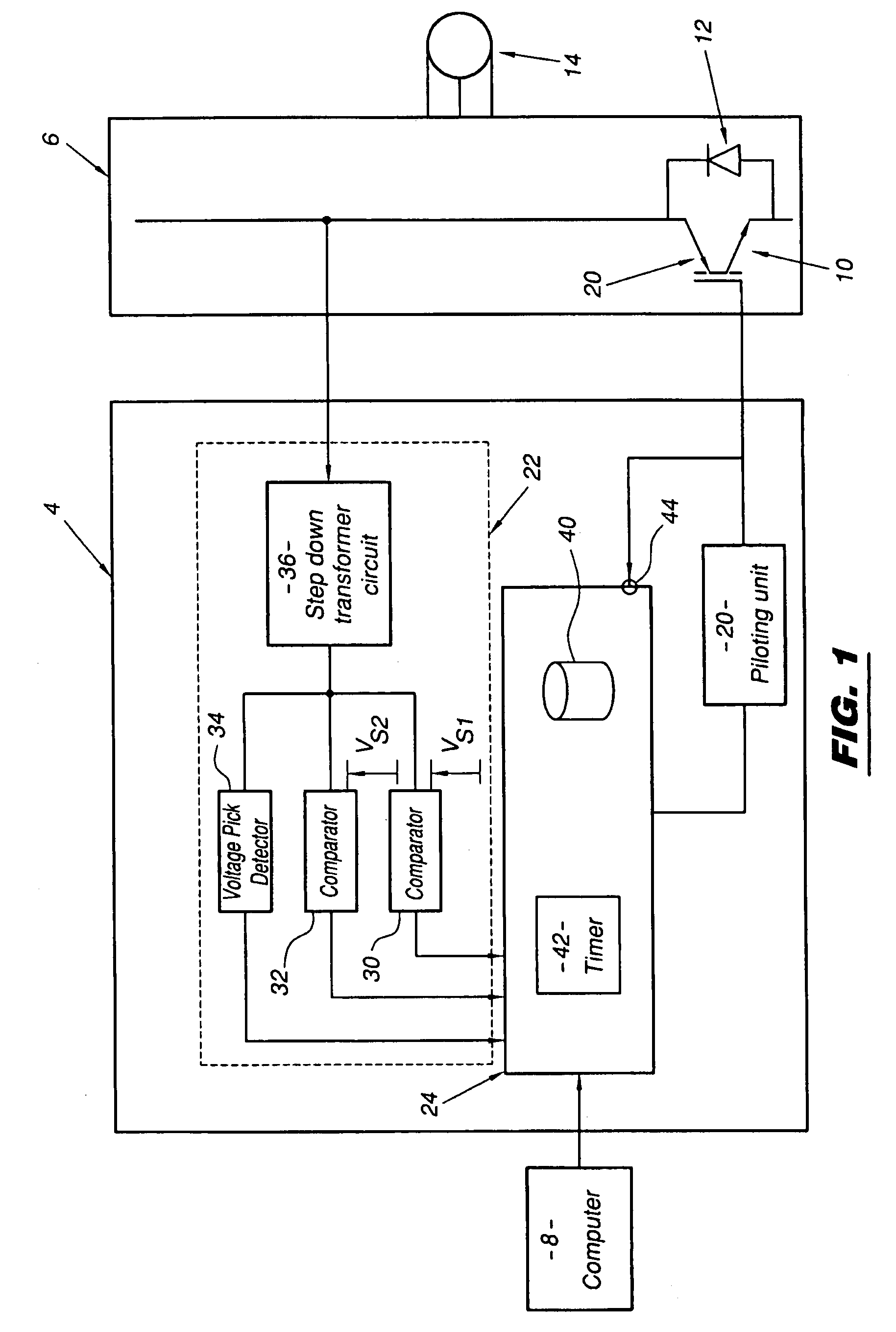
[0043]Referring now to the drawings, FIG. 1 shows an electronic igniter 4 adapted to control the power transistors of an electronic commutation device 6 as a function of orders transmitted by a computer 8.

[0044]The commutation device 6 is for example a conventional three-phase inverter made from IGBT (Insulated Gate Bipolar Transistor)power transistors 10 and diodes 12 connected in anti-parallel position between the collector and the emitter of each of the transistors 10.

[0045]The transistor 10 is typically capable of commuting currents going up to 1000 A and of withstanding a voltage VCE between the collector and the emitter in the non-conducting state, i.e. in the open state, included between 250 and 4000 V. In the conducting state, i.e. in the closed state, the voltage VCE is generally less than 5 V.

[0046]In order to simplify the illustration, only one of these transistors 10 and one of these diodes 12 are shown here.

[0047]This three-phase inverter 6 is for example intended to su...


PUM


Abstract

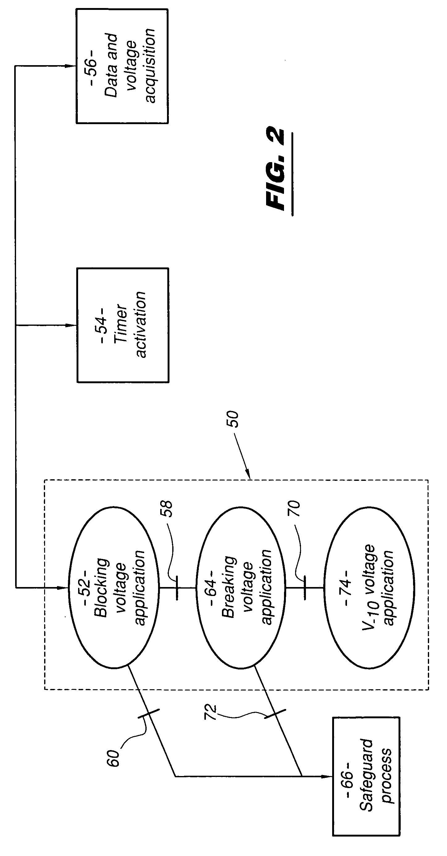
The process for controlling an electronic power component for piloting an opening and / or closure of this component. The piloting process includes a plurality of steps for controlling the application of a succession of different commutation voltages on a control electrode of the electronic power component between an instant when the piloting process begins and an instant when either the opening or the closure of the electronic power component is to stop. Passage from one commutation voltage to a successive commutation voltage in this piloting process is automatically effected as soon as a corresponding condition of passage is satisfied. The process further includes a step of interrupting the piloting process and immediately triggering off a process for safeguarding the integrity of the electronic power component if the component does not react to a commutation voltage within a predetermined time for the commutation voltage.

Description

FIELD OF THE INVENTION[0001]The present invention relates to a process and a system for controlling an electronic power component.[0002]More precisely, this invention relates to a control process comprising a process for piloting the opening and / or closure of the electronic power component, the piloting process comprising a plurality of steps for controlling the application of a succession of different commutation voltages on a control electrode of said component between the instant when the piloting process begins and the instant when the opening and / or closure of the electronic power component must stop, the passage from one step to the following step in this piloting process being effected automatically as soon as a corresponding condition of passage is satisfied.BACKGROUND OF THE INVENTION[0003]Such control processes are known under the terms of CATS control and disclosed for power transistors in “CATS Control: Assessment of the Robustness and Application to the Servo-Control of...

Claims


Application Information

Patent Timeline
Patent Type & Authority Patents(United States)
IPC IPC(8): H02H3/027H02H3/247H03K17/082H03K17/16
CPCH03K17/0828H03K17/166
Inventor LEPAGE, JEAN-PIERRE
Owner ALSTOM TRANSPORT TECH SAS
Learn More