Magnetic sensing apparatus

a sensing apparatus and magnetic field technology, applied in the field of sensing devices and techniques, can solve the problems of missing an excessive number of output pulses, a large amount of rotational vibration or jitter on targets,

Active Publication Date: 2007-09-18
HONEYWELL INT INC
View PDF6 Cites 3 Cited by
  • Summary
  • Abstract
  • Description
  • Claims
  • Application Information

AI Technical Summary

Benefits of technology

[0009]The aforementioned aspects and other objectives and advantages can now be achieved as described herein. A magnetic sensing apparatus is described herein, which includes a first magnetic transducer separated spatially from a second magnetic transducer and proximate to a target. The magnetic sensing apparatus further includes a direction decoding circuit associated with the first and second magnetic transducers, wherein the direction decoding circuit produces output pulses that provide data indicative of a rotation of the target while rejecting rotational vibration signals associated with the target during a rotational detection of the target utilizing the first and second magnetic transducers without producing erroneous output pulses or missing an excessive number of the output pulses during speed and rotational detection operations thereof.
[0010]The direction decoding circuit can be configured to include a first sub-circuit associated with the first magnetic transducer, wherein the first sub-circuit comprises a first amplifier in association with a first peak detector and a first comparator, and a second sub-circuit associated with the second magnetic transducer, wherein the second sub-circuit comprises a second amplifier in association with a second peak detector and a second comparator, wherein the first and second sub-circuits generate output pulses respectively associated with the first and second magnetic transducers. Additionally, a peak detector reset circuit can be incorporated into the direction decoding circuit that prevents the direction decoding circuit from missing the excessive number of the output pulses during speed and rotational detection operations thereof.

Problems solved by technology

One of the problems with detecting targets, particularly rotational targets (e.g., a rotating shaft), and using magnetic sensing devices is that such targets typically possess a large amount of rotational vibration or jitter along with wobble or run-out.
Such features can distort the output signals generated by the magnetic sensor utilized, thereby producing erroneous output pulses or resulting in missing an excessive number of output pulses.

Method used


Image

  • Magnetic sensing apparatus
  • Magnetic sensing apparatus
  • Magnetic sensing apparatus

Examples


Embodiment Construction

[0018]The particular values and configurations discussed in these non-limiting examples can be varied and are cited merely to illustrate at least one embodiment of the present invention and are not intended to limit the scope thereof.

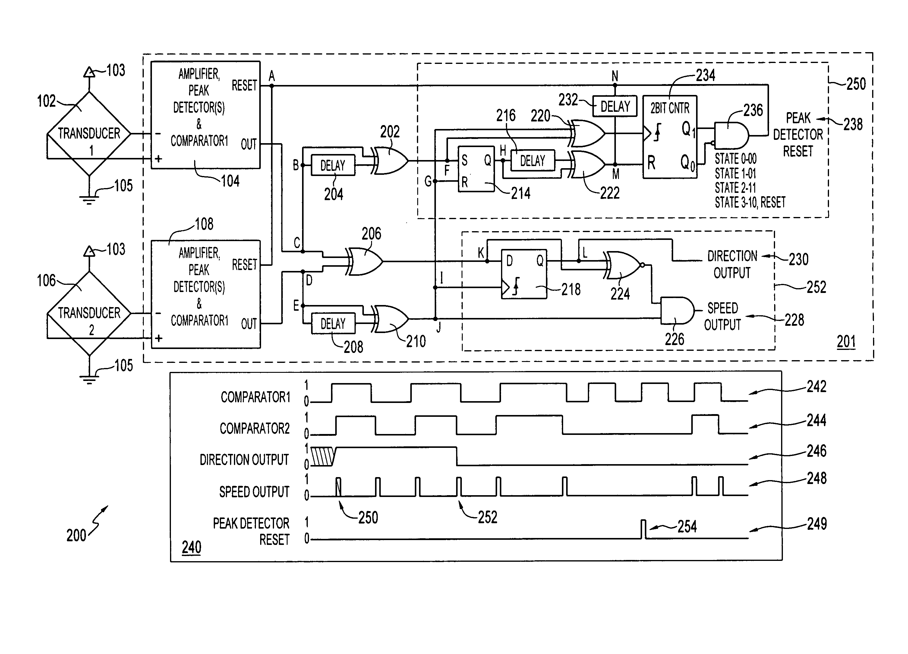
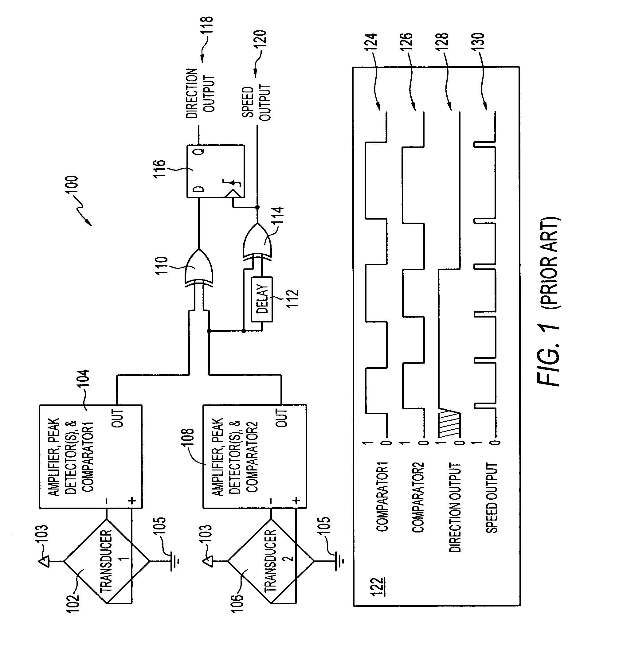
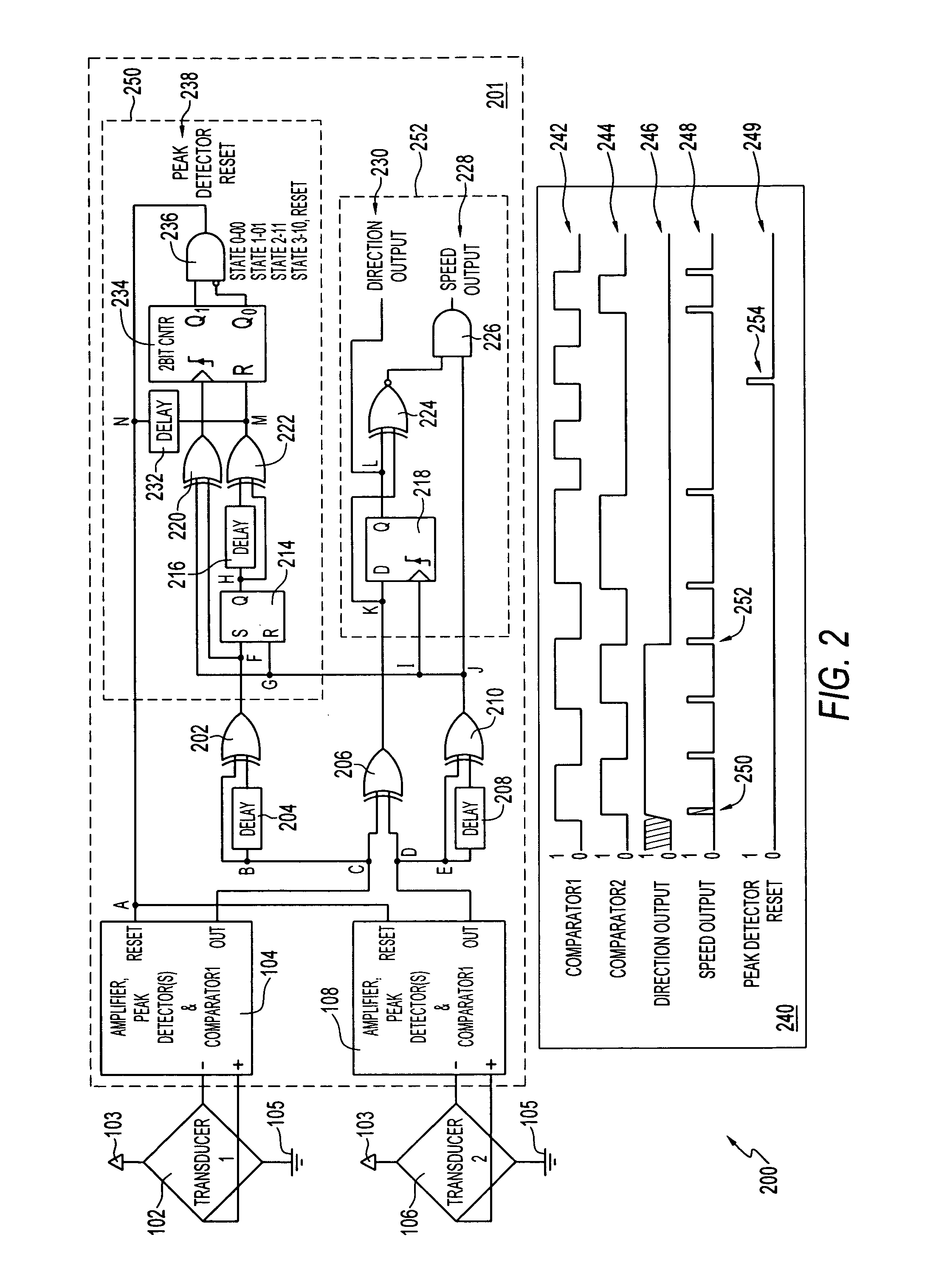
[0019]FIG. 1 illustrates a prior art direction decoding circuit 100 that includes a first magnetic transducer 102 connected to power (Vcc) 103 and ground 105. Note that apparatus 100 is described and depicted herein for illustrative and edification purposes only and is not considered a limitation to the preferred embodiment also described herein. Also note that in FIGS. 1-2, identical or similar parts or elements are generally indicated by identical reference numerals.

[0020]In general, the first magnetic transducer 102 is connected to a first sub-circuit 104 that includes a first amplifier in association with a first peak detector and a first comparator. Circuit 100 additionally includes a second sub-circuit 108 associated a second magnetic transducer 1...


PUM


Abstract

A magnetic sensing apparatus includes a first magnetic transducer separated spatially from a second magnetic transducer and proximate to a target and a direction decoding circuit associated with the first and second magnetic transducers, wherein the direction decoding circuit produces output pulses that provide data indicative of a rotation of the target while rejecting rotational vibration signals associated with the target during a rotational detection of the target utilizing the first and second magnetic transducers without producing erroneous output pulses or missing an excessive number of the output pulses during speed and rotational detection operations thereof.

Description

TECHNICAL FIELD[0001]Embodiments are generally related to sensing devices and techniques. Embodiments are also related to rotational sensing devices and systems. Embodiments are additionally related to magnetic sensors and magnetoresistive components thereof.BACKGROUND OF THE INVENTION[0002]Various sensors are known in the magnetic-effect sensing arts. Examples of common magnetic-effect sensors may include, for example, Hall Effect and magnetoresistive technologies. Generally, these magnetic-effect sensors can respond to the change of magnetic field as influenced by the presence or absence of a ferromagnetic target object of a designed shape that passes through or by the sensory field of the magnetic-effect sensor.[0003]When acting as a transducer, the magnetic-effect sensor generally outputs an electrical signal representative of the sensed magnetic field. The electrical signal can vary in amplitude and width so as to correspond to the shape, e.g., a profile, of the target object. ...

Claims


Application Information

Patent Timeline
Patent Type & Authority Patents(United States)
IPC IPC(8): G01B7/30G01R33/07
CPCG01D5/24476G01D2205/85
Inventor CHILCOTE, JASON M.FURLONG, GREGORY R.MURDOCK, JOSEPH K.MEYERS, AARON J.
Owner HONEYWELL INT INC
Why Eureka
Try Eureka