Dual-Clutch Tranmission

a dual-clutch transmission and transmission shaft technology, applied in mechanical equipment, transportation and packaging, gear shift forks for the six-gear and reverse-gear synchronizers, etc., can solve the problems of preventing the realization of a compact structural form, affecting the realization of compact structural forms, and affecting the operation of the gear shift fork. , to achieve the effect of less number of teeth, and optimal gear siz

Active Publication Date: 2015-11-26
CHERY AUTOMOBILE CO LTD +1
View PDF7 Cites 1 Cited by
  • Summary
  • Abstract
  • Description
  • Claims
  • Application Information

AI Technical Summary

Benefits of technology

[0044]With above technical solutions according to the present invention, two input shafts and two driving shafts are used to configure seven forward gears and one reverse gear, thus omitting one reverse gear shaft. Meanwhile, by providing a first-gear driven gear and a second-gear driven gear on a driving shaft having a primary reduction driving gear with relatively less teeth number and providing a sixth-gear driven gear and a seventh-gear driven gear on another driving shaft having a primary reduction driving gear with relatively more teeth number, an optimal configuration of the gear size and the transmission ratio for each gear is realized. Therefore, this arrangement is compact, simple and reasonable in structure, and there are fewer numbers of gears, shafts and synchronizer parts. As the diameter of the first-gear, second-gear and third-gear driven gears is large, engagement sleeves of the synchronizers for these gears may be arranged inside the gears, which greatly save an axial space in conjunction with the reasonable arrangement of the position of the gears. As one reverse gear shaft is omitted, the saved space facilitates the arrangement of the gear shaft fork mechanism.

Problems solved by technology

In such a dual-clutch transmission, the arrangement of providing a specific shaft for the reverse gear will largely limit the arrangement of a gear shift mechanism and the overall structural arrangement of the transmission, preventing the realization of a compact structural form.
This transmission has two input shafts and three output shafts in total, which hampers the realization of a compact structural form.
In addition, because this dual-clutch transmission employs five synchronizers, and a six-gear and reverse-gear synchronizer works only with its half side, it results in a large number of parts and a complicate structure of a gear shift fork for the six-gear and reverse-gear synchronizer.

Method used


Image

  • Dual-Clutch Tranmission
  • Dual-Clutch Tranmission
  • Dual-Clutch Tranmission

Examples


embodiment 1

[0072]In order to solve the problems in the prior art and overcome the deficiencies thereof, and to achieve the inventive purpose of optimizing the structure to be simpler, more reasonable and compact, the present invention adopts the following technical solutions.

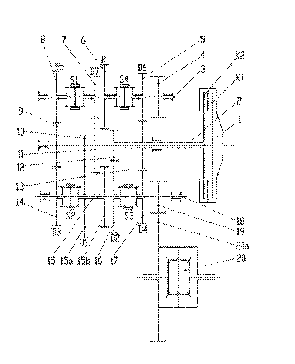
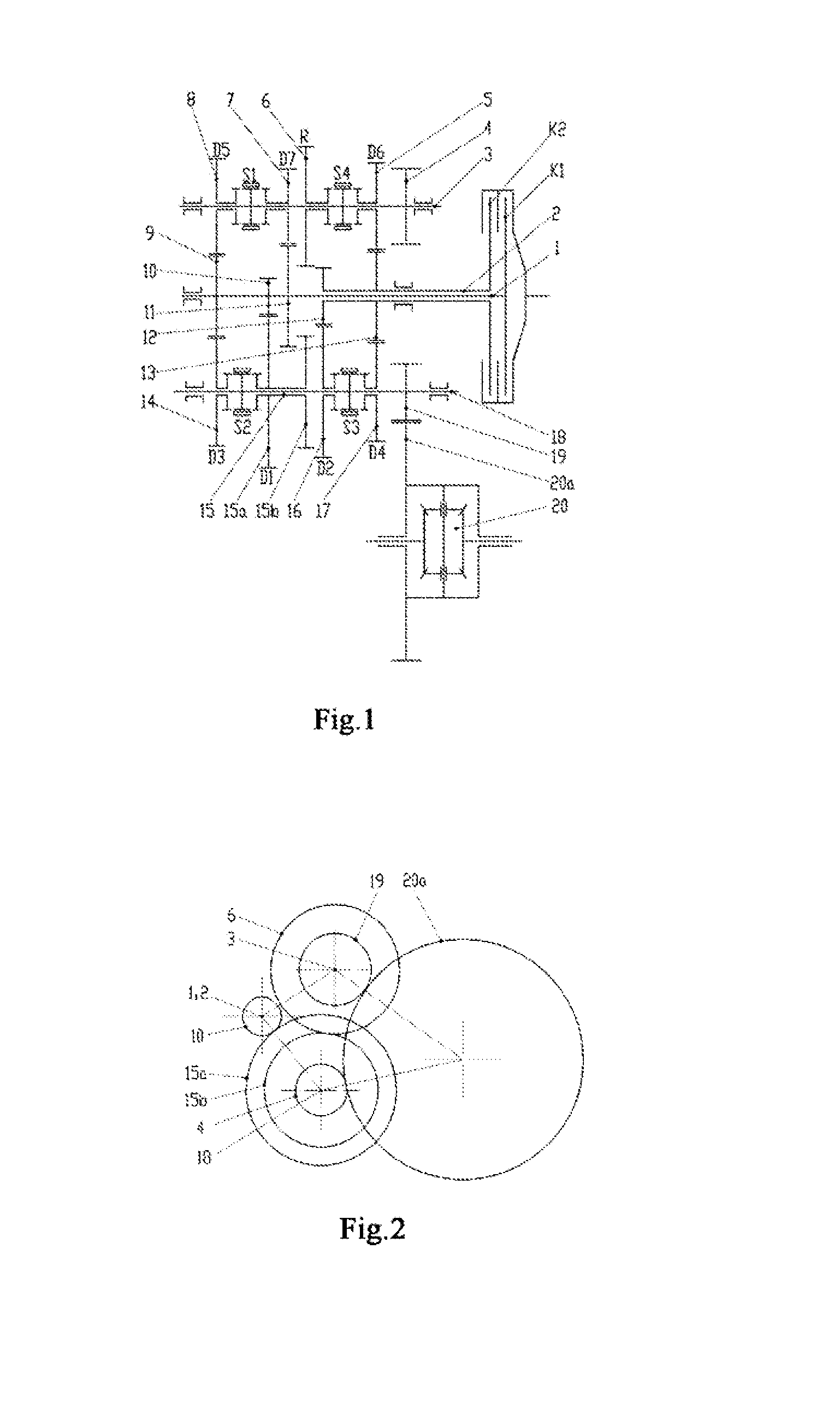
[0073]As shown in FIG. 1 and FIG. 2, in the dual-clutch transmission according to the present invention:

[0074]a third-gear and fifth-gear driving gear 9, a first-gear driving gear 10 and a seventh-gear driving gear 11 are fixed on the first input shaft 1 in sequence;

[0075]a second-gear driving gear 12 and a fourth-gear and six-gear driving gear 13 are fixed on the second input shaft 2 in sequence;

[0076]the third-gear and fifth-gear driving gear 9 is located on a rear side of the transmission far away from the dual clutches, and the fourth-gear and six-gear driving gear 13 is located on a front side of the transmission close to the dual clutches;

[0077]a third-gear driven gear 14, a first-gear driven gear 15, a second-gear d...

embodiment 2

[0097]In order to achieve the same object as that of above technical solutions, the present invention employs the following technical solutions.

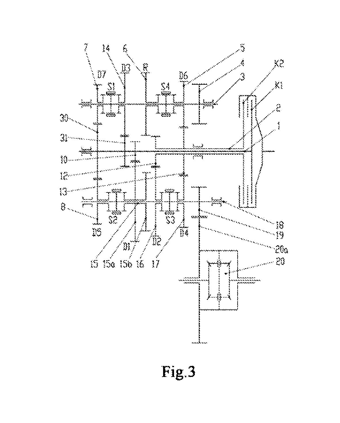
[0098]As shown in FIG. 2 and FIG. 3, in a dual-clutch transmission according to the present invention:

[0099]a fifth-gear and seventh-gear driving gear 30, a third-gear driving gear 31 and a first-gear driving gear 10 are fixed on the first input shaft 1 in sequence;

[0100]a second-gear driving gear 12 and a fourth-gear and sixth-gear driving gear 13 are fixed on the second input shaft 2 in sequence;

[0101]the fifth-gear and seventh-gear driving gear 30 is located on a rear side of the transmission far away from the dual clutches, and the fourth-gear and sixth-gear driving gear 13 is located on a front side of the transmission close to the dual clutches;

[0102]a fifth-gear driven gear 8, a first-gear driven gear 15, a second-gear driven gear 16 and a fourth-gear driven gear 17 are arranged on the first driving shaft 18 in sequence, and a first-g...


PUM


Abstract

Disclosed is a dual-clutch transmission, using two input shafts (1, 2) and two driving shafts (3, 18), realizing seven forward gears (D1, D2, D3, D4, D5, D6, D7) and a reverse gear (R), eliminating a special reverse gear shaft for the reverse gear (R), and using eight synchronizers (S1, S2, S3, S4) to control the switching of all of the eight gears, namely the seven forward gears (D1, D2, D3, D4, D5, D6, D7) and the reverse gear (R), wherein part of the gears share a driving gear, so that the quantity of total parts and the axial length of the transmission are reduced; since the diameters of driven gears (14, 15, 16) of low-speed gears are relatively large, engagement sleeves of the corresponding synchronizers (S2, S3) can be arranged on the inner sides of the driven gears (14, 15, 16) according to structural arrangement requirements, so that an axial space is greatly saved; and the reverse gear shaft and a gear thereon are eliminated, the saved space facilitates the arrangement of a gear shaft fork mechanism, the supporting point of a gear shift fork can be close to the centers of the driving shafts (3, 18) and a gear shift execution mechanism in the absence of obstructions of the reverse gear shaft and the gear thereon, which is beneficial to the force distribution of the shift fork mechanism.

Description

TECHNICAL FIELD[0001]The present invention belongs to a technical field of automobile construction, and relates to a structure of an automobile power system. More particularly, the present invention relates to a dual-clutch transmission.BACKGROUND OF THE PRESENT INVENTION[0002]Since the dual-clutch transmission adopts a dual-clutch system and a conventional fixed-axle gear transmission, it has a higher transmission efficiency, a shorter system power interruption duration during a gear shift, and favorable driving comfort and fuel economy. The Dual-clutch transmission has gradually become a hot spot in the development of the transmission industry since it was successfully commercialized and installed in automobiles by Volkswagen.[0003]A Chinese Patent CN 102084153A discloses a dual-clutch transmission having two input shafts connected to a first clutch or a second clutch, respectively. Two driving shafts, provided above and below the input shafts, transmit a torque to a differential ...

Claims


Application Information

Patent Timeline
Patent Type & Authority Applications(United States)
IPC IPC(8): F16H3/087F16H37/08
CPCF16H3/087F16H2200/0056F16H37/08F16H3/006F16H2003/0931F16H2003/0933F16H2200/2076
Inventor LIN, JIAN
Owner CHERY AUTOMOBILE CO LTD
Why Eureka
Try Eureka