Method and system for testing a signal path having an operational signal

a signal path and operational signal technology, applied in the field of electronic system testing, can solve the problems of difficult to reproduce intermittent failures in flight, adverse effects on the reliability of electronic systems, and difficulty in testing aircraft wiring

Active Publication Date: 2007-09-18
UNIV OF UTAH RES FOUND
View PDF13 Cites 40 Cited by
  • Summary
  • Abstract
  • Description
  • Claims
  • Application Information

AI Technical Summary

Benefits of technology

[0009]It has been recognized it would be advantageous to develop a technique for testing signal paths that can be used while an operational signal is present. An “operational signal” refers a signal present within the system during operation. Accordingly, the inventive technique can be performed without injecting a test signal into the signal path.
[0011]There are numerous applications for the method. For example, because the method may be performed while an operational signal is present, detection of intermittent anomalies in the signal path is enhanced. The method can be performed continuously, hence intermittent anomalies, such as open circuits, short circuits, and arc faults, can be detected and recorded when they occur. Moreover, by estimating the correlation of the operational signal, no additional test signal need be injected, reducing the possibility of interference to the operational signal.

Problems solved by technology

Unfortunately, the reliability of an electronic system can be adversely affected by an anomaly in one of its signal paths.
For example, aircraft provide a particularly poignant example: failures in the wiring of an aircraft can cause catastrophic results.
Aircraft wiring can prove difficult to test, however, at it is often inaccessible.
Furthermore, intermittent failures can occur in flight that are difficult to reproduce under the differing vibration, altitude, temperature, and humidity conditions that occur on the ground.
Productive time is lost when aircraft must be grounded; yet, technicians may be unable to find the cause of a failure.
Testing of signal paths in electronic systems can be difficult, however, as wires are often inaccessible, hidden behind panels, wrapped in protective jackets, or otherwise difficult to access.
Removal of wires for testing or inspection can cause damage, and even if the wires are functioning properly upon inspection, reinsertion of the wires into the system can cause damage.
If an operational signal is present, the measurement may be erroneous.
More sophisticated techniques involve injecting other types of test signals into the signal path, and can be disrupted if an operational signal is present.
Furthermore, injecting a test signal into the signal path while the system is operational can result in disruption to the system.
Shutting down the system for testing can be both inconvenient and expensive if revenues are lost while the system is shut down.
Furthermore, some types of intermittent faults may be very difficult to detect in this manner.

Method used


Image

  • Method and system for testing a signal path having an operational signal
  • Method and system for testing a signal path having an operational signal
  • Method and system for testing a signal path having an operational signal

Examples


Embodiment Construction

[0031]Reference will now be made to the exemplary embodiments illustrated in the drawings, and specific language will be used herein to describe the same. It will nevertheless be understood that no limitation of the scope of the invention is thereby intended. Alterations and further modifications of the inventive features illustrated herein, and additional applications of the principles of the inventions as illustrated herein, which would occur to one skilled in the relevant art and having possession of this disclosure, are to be considered within the scope of the invention.

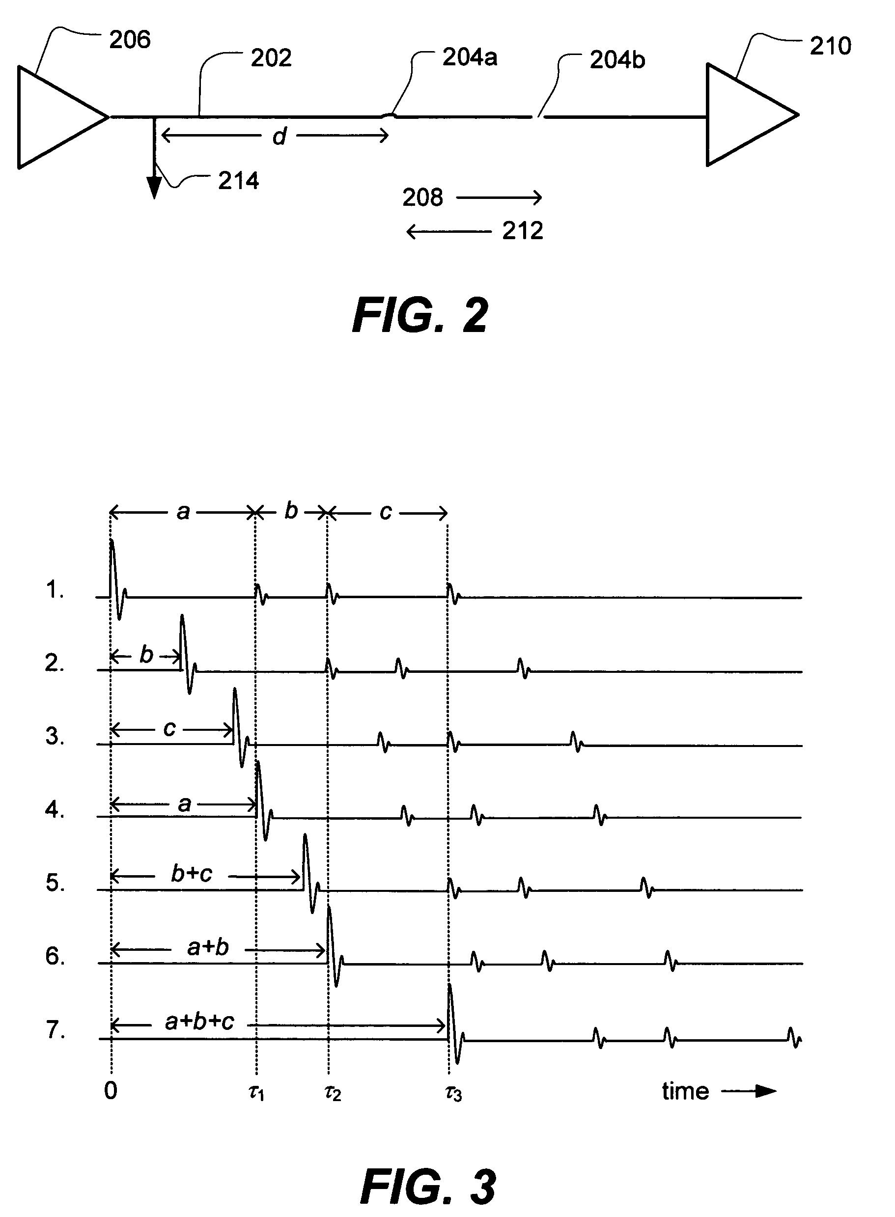
[0032]First, in order to understand the presently disclosed inventive concepts, a review of the principles of reflectometry and correlation may prove helpful. Time domain reflectometry (TDR) involves injecting a short duration pulse into a signal path under test. The pulse will propagate in a forward direction along the signal path, yet small amounts of energy from the pulse will be reflected back by impedance di...


PUM


Abstract

A technique for testing a signal path while an operational signal is present is disclosed. The technique may be performed without injecting a test signal into the signal path by using an operational signal already present in the signal path. A method of testing a signal path includes receiving an operational signal from the signal path and estimating a correlation of the operational signal. A system for testing a signal path includes an extractor configured to extract a sample of the operational signal when coupled to a signal path and a correlator configured to estimate a correlation of the operational signal. Various properties of the signal path may be determined using the technique.

Description

[0001]This application is a continuation-in-part of copending PCT Application No. PCT / US2004 / 008165 entitled “Method and System for Testing A Signal Path Having an Operational Signal” filed on Mar. 17, 2004 which claims the benefit of U.S. Application No. 60 / 455,788 filed on Mar. 18, 2003 entitled “Noise Domain Reflectometer Apparatus and Method for Determining the Integrity and / or Lengths of Signal Paths.”[0002]This application is also continuation-in-part of copending U.S. application Ser. No. 11 / 133,145 filed on May 18, 2005 entitled “Device and Method for Detecting Anomolies in a Wire and Related Sensing Methods” which is a continuation-in-part of PCT Application No. PCT / US03 / 37233 filed on 19 Nov. 2003 entitled “Device and Method for Detecting Anomolies in a Wire and Related Sending Methods” which claims the benefit of U.S. Application No. 60 / 427,737 filed on 19 Nov. 2002 entitled “Handheld Device for Detecting Open, Short and Location of Anomaly on a Wire,” U.S. Application No...

Claims


Application Information

Patent Timeline
Patent Type & Authority Patents(United States)
IPC IPC(8): G01R31/11H04W24/00
CPCG01R31/11H03H11/126H04W24/00
Inventor FURSE, CYNTHIALO, CHET
Owner UNIV OF UTAH RES FOUND
Why Eureka
Try Eureka