Electrode arrangement for electrical stimulation of biological material, and a multi-electrode array for use in such an electrode arrangement

a biological material and electrode arrangement technology, applied in external electrodes, sensors, artificial respiration, etc., can solve the problems of irreversible tissue damage, detection of transient processes above all, and none of the known methods are optimal, and achieve the effect of reliable suppression of undesired reactions

Inactive Publication Date: 2007-09-18
RETINA IMPLANT GMBH
View PDF14 Cites 25 Cited by
  • Summary
  • Abstract
  • Description
  • Claims
  • Application Information

AI Technical Summary

Benefits of technology

[0015]In view of the above, it is an object of the present invention to specify an electrode arrangement of the type mentioned at the outset which on the one hand provides many degrees of freedom in the configuration of the stimulus signals and, on the other hand, permits reliable suppression of undesired reactions.

Problems solved by technology

If the polarization voltage exceeds a certain threshold value, undesired redox reactions occur which can lead to irreversible tissue damage.
None of the known methods is optimum, however.
Precisely the last-mentioned measures have the disadvantage that transient processes are above all detected, whereas no account is taken of a static electrode polarization rising in the course of time.
Consequently, it is necessary in practice to take account of safety reserves in the dimensioning, and this renders optimum stimulation of the cell tissue difficult.
The regular or continuous discharge of the interface capacitor impairs the degrees of freedom in the temporal dimensioning of the stimulus signals.
However, if a multiplicity of electrodes, that is to say a multi-electrode array, is used for the stimulation of the cell tissue such as, for example, in the case of a retina implant, real time monitoring for the avoidance of undesired reactions is very complicated.

Method used


Image

  • Electrode arrangement for electrical stimulation of biological material, and a multi-electrode array for use in such an electrode arrangement
  • Electrode arrangement for electrical stimulation of biological material, and a multi-electrode array for use in such an electrode arrangement
  • Electrode arrangement for electrical stimulation of biological material, and a multi-electrode array for use in such an electrode arrangement

Examples


Embodiment Construction

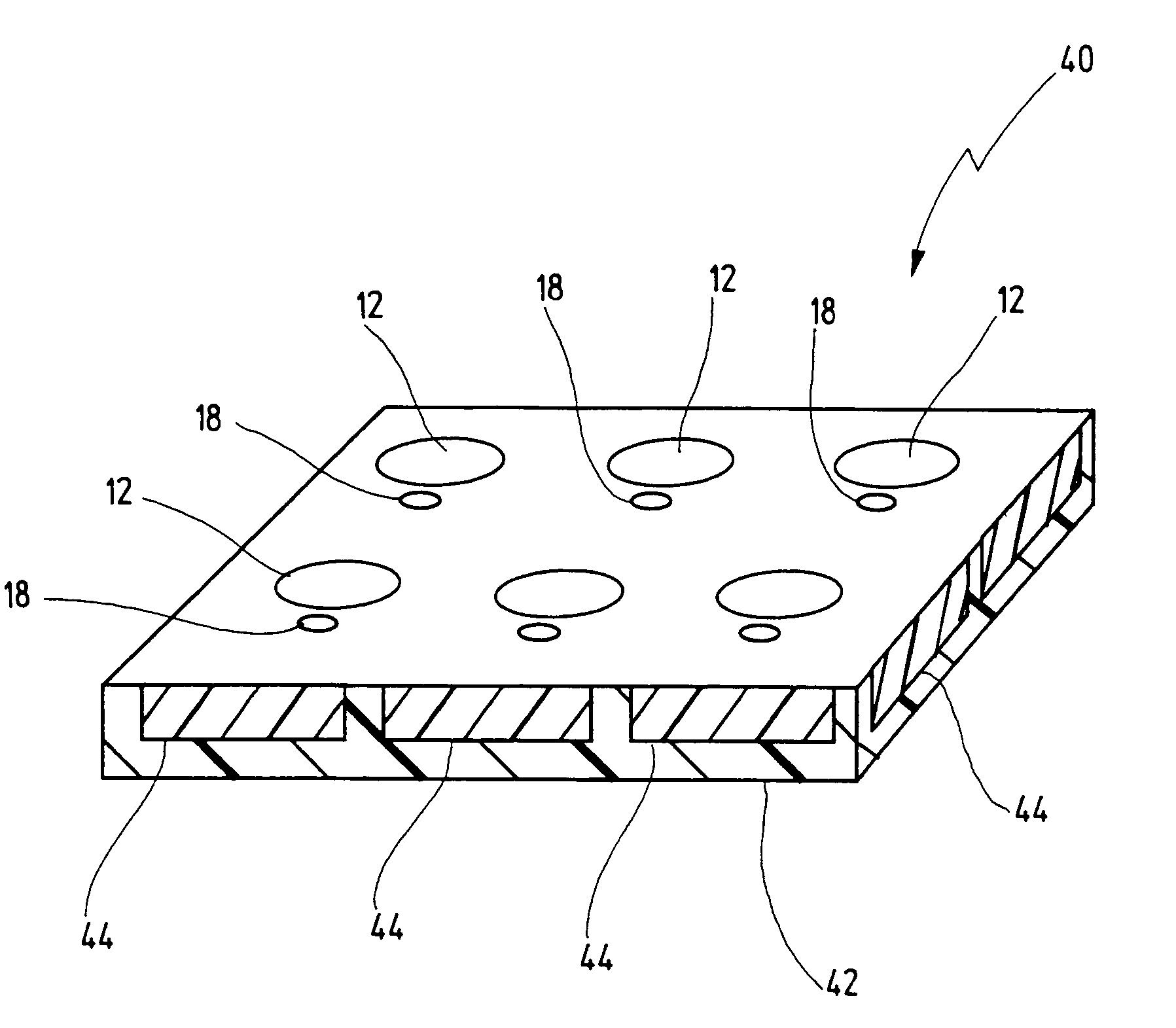
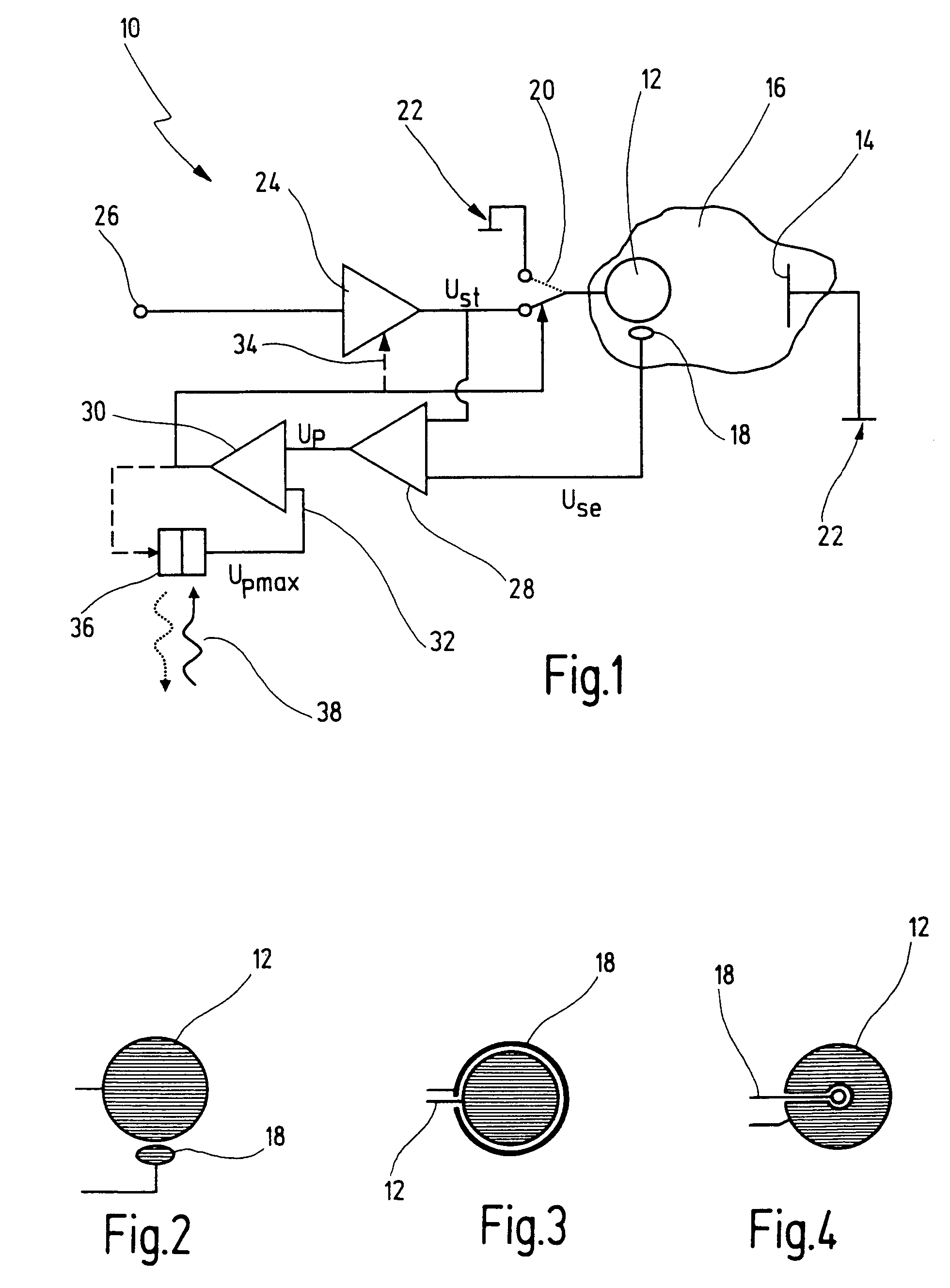
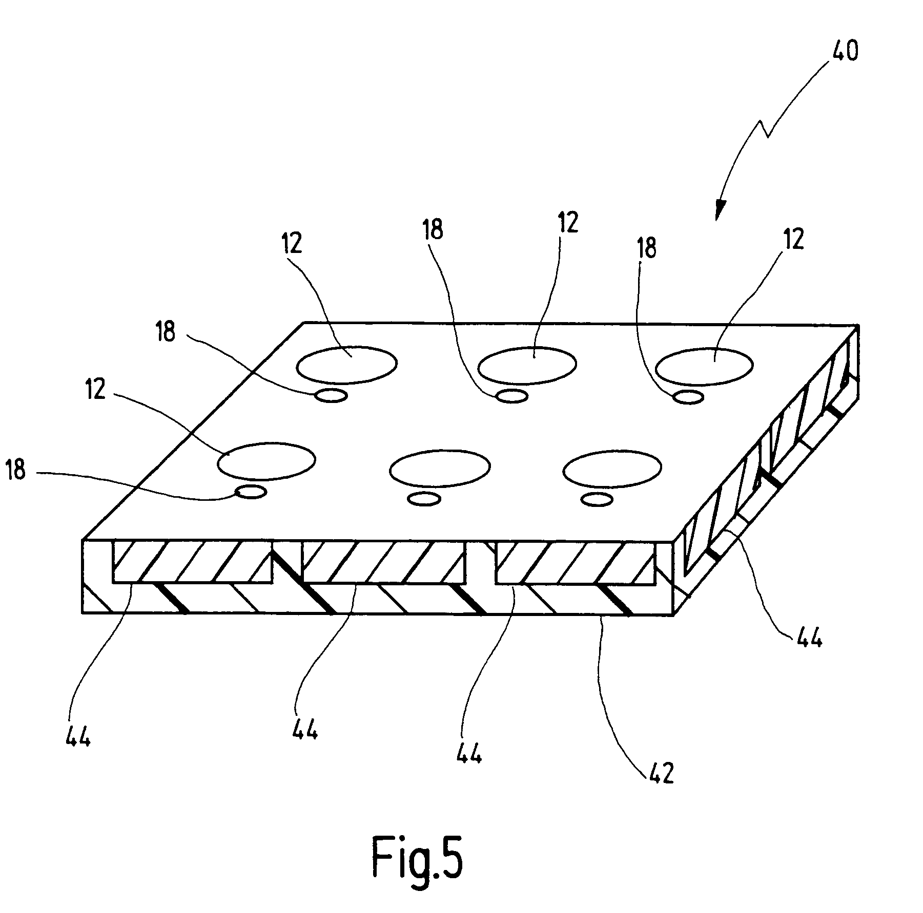
[0059]An electrode arrangement according to the invention is denoted in FIG. 1 in its entirety by the reference numeral 10.

[0060]The electrode arrangement 10 includes a stimulation electrode 12 which is produced using planar technology. However, the invention is not restricted thereto. In other exemplary embodiments, the stimulation electrode and the sensor electrode are arranged in a “3-D arrangement”, that is to say in mutually offset planes. The reference numeral 14 denotes a counter electrode which forms the counter pole (ground) for the stimulation electrode 12. The two electrodes 12, 14 serve the purpose of electrically stimulating biological material, in the present example a cell tissue 16, in a way known per se.

[0061]In a preferred embodiment of the invention, the cell tissue 16 is a tissue in the region of the retina of the human eye. The stimulation electrode 12 and the further subsequently described constituents of the electrode arrangement 10 are implanted in this case ...


PUM


Abstract

An electrode arrangement for electrical stimulation of biological material has at least one stimulation electrode via which the biological material can be fed a stimulus signal. Furthermore, a counter electrode is present which forms a counter pole to the stimulation electrode, one sensor electrode is provided with the aid of which it is possible to determine a polarization voltage across the stimulation electrode.

Description

CROSS-REFERENCES TO RELATED APPLICATIONS [0001]This application is a continuation of copending international patent application PCT / EP02 / 10972 filed on Oct. 1, 2002 and designating the U.S., which was not published under PCT Article 21(2) in English, and claims priority of German patent application DE 101 51 650.9 filed on Oct. 17, 2001, which is incorporated herein by reference.BACKGROUND OF THE INVENTION [0002]1. Field of the Invention[0003]The present invention relates to an electrode arrangement for electrical stimulation of biological material, having at least one stimulation electrode via which the biological material can be fed a stimulus signal, and having at least one counter electrode which forms a counter pole to the stimulation electrode.[0004]The invention relates furthermore to a multi-electrode array for use in such an electrode arrangement.[0005]2. Related Prior Art[0006]An electrode arrangement of the said type and a corresponding multi-electrode array are disclosed...

Claims


Application Information

Patent Timeline
Patent Type & Authority Patents(United States)
IPC IPC(8): A61N1/05A61N1/08A61N1/36A61B5/296A61F2/14
CPCA61N1/0543A61N1/36046
Inventor STETT, ALFREDNISCH, WILFRIEDSTELZLE, MARTINZRENNER, EBERHART
Owner RETINA IMPLANT GMBH
Why Eureka
Try Eureka