Liquid ejecting head, method for manufacturing the same and liquid ejecting apparatus

a technology of liquid ejector and liquid ejector, which is applied in the direction of piezoelectric/electrostrictive transducers, inking apparatuses, transducer types, etc., can solve the problems of gradual change of ejection characteristic of ink droplets, hard deposited protection film, and gradual corrosion

Inactive Publication Date: 2011-09-29
SEIKO EPSON CORP
View PDF4 Cites 12 Cited by
  • Summary
  • Abstract
  • Description
  • Claims
  • Application Information

AI Technical Summary

Benefits of technology

An advantage of some aspects of the invention is to provide a liquid ejecting head which can suppress a wall surface of a liquid flow path from being corroded away by liquid and desirably maintain an ejection characteristic of liquid droplets for a long period of time, a method for manufacturing the liquid ejecting head and a liquid ejecting apparatus.

Problems solved by technology

The silicon oxide is a material which is relatively hard to be corroded away by ink but is gradually corroded away when used for a long period of time.
Accordingly, there arises a risk that an ejection characteristic of ink droplets is gradually changed when used for a long period of time.
However, there is a portion where a protection film is hard to be deposited, such as a boundary portion between the flow path formation substrate and the vibration plate.
In such a case, there arises a risk that the vibration plate and the like is not sufficiently suppressed from being corroded away by ink.
Further, there is a risk that a displacement characteristic of the vibration plate is changed by the protection film and variation happens easily on an ejection characteristic of ink droplets of each head.
It is to be noted that such problem is caused to happen not only on the ink jet recording head which ejects ink droplets but on other liquid ejecting heads which ejects liquid droplets other than ink, of course.

Method used


Image

  • Liquid ejecting head, method for manufacturing the same and liquid ejecting apparatus
  • Liquid ejecting head, method for manufacturing the same and liquid ejecting apparatus
  • Liquid ejecting head, method for manufacturing the same and liquid ejecting apparatus

Examples


first embodiment

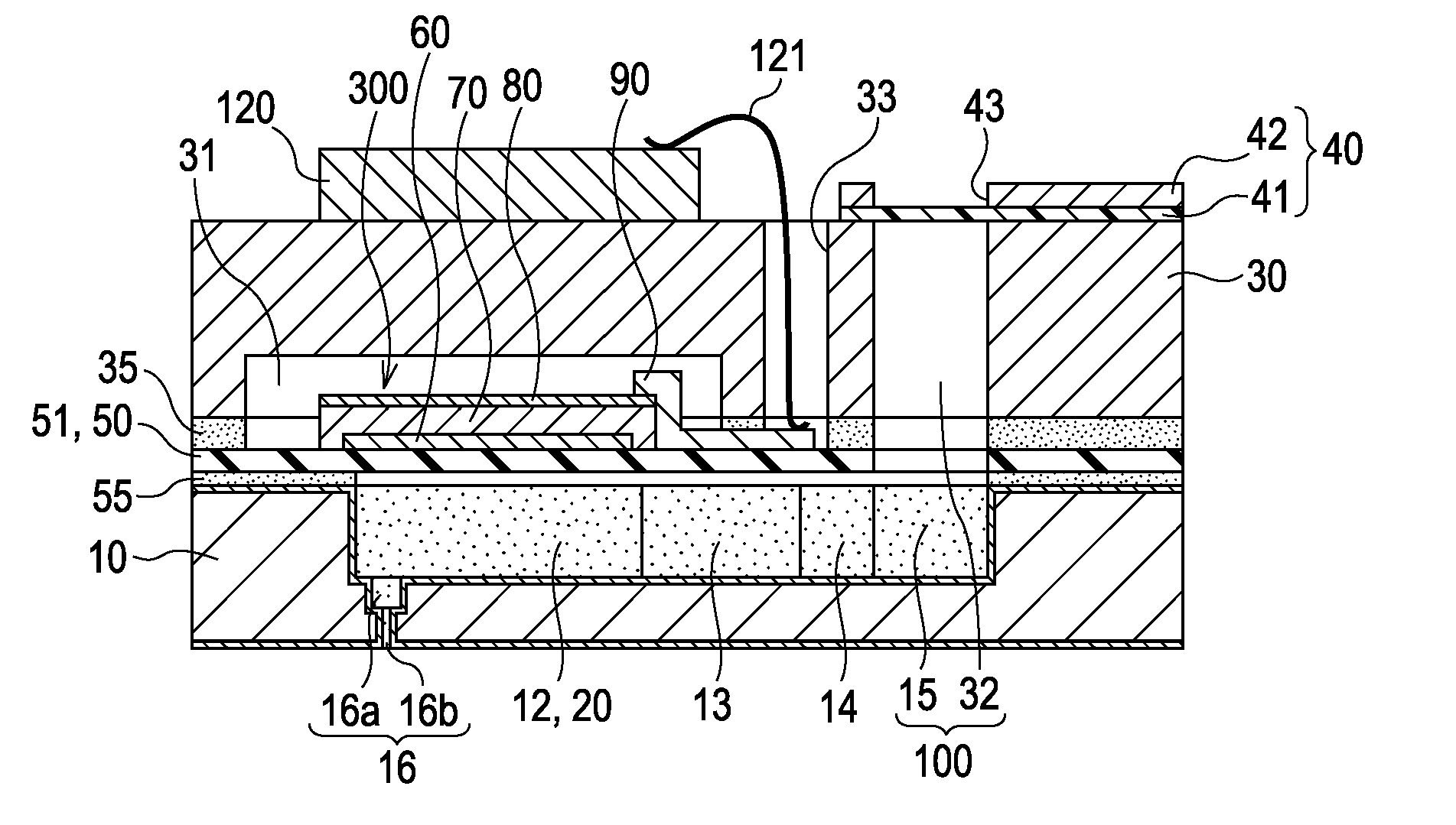
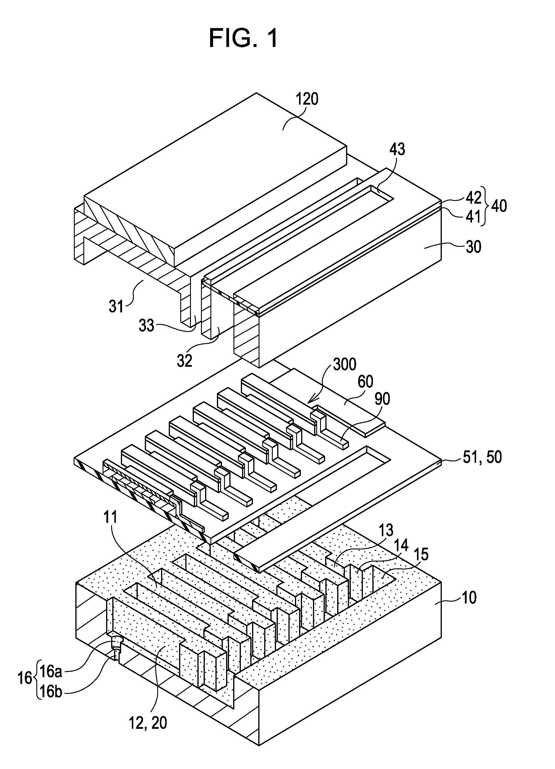
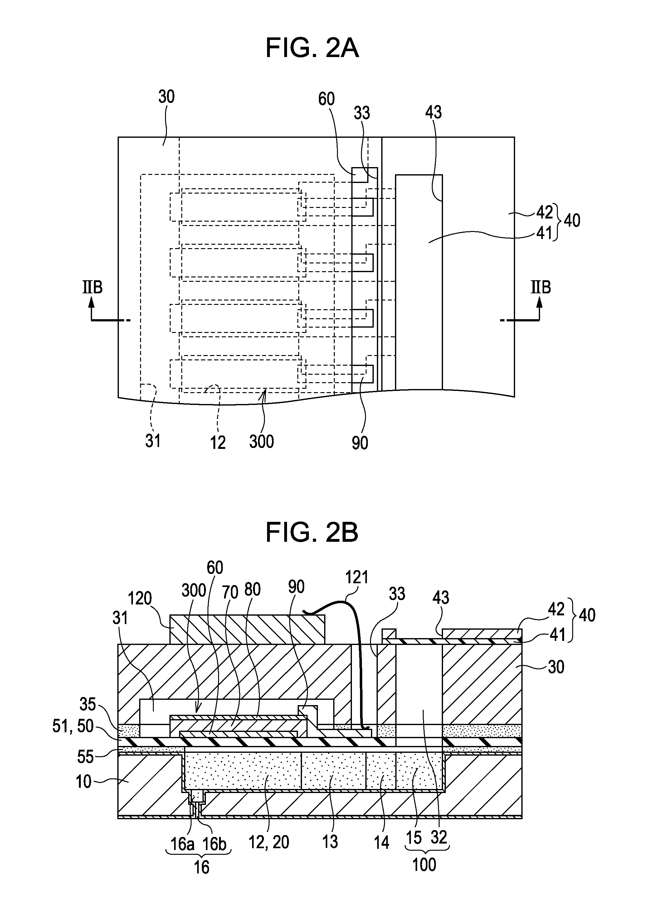
FIG. 1 is an exploded perspective view illustrating an ink jet recording head as an example of a liquid ejecting head according to the first embodiment of the invention. FIGS. 2A and 2B are a plan view and a cross-sectional view of FIG. 1, respectively.

As shown in FIG. 1 and FIGS. 2A and 2B, a plurality of pressure generation chambers 12 are arranged in parallel on a flow path formation substrate 10 constituting an ink jet recording head in a width direction thereof. The plurality of pressure generation chambers 12 are partitioned by separation walls 11. Further, ink supply paths 13 and communicating paths 14 are provided at the side of one ends of the pressure generation chambers 12 in a longitudinal direction on the flow path formation substrate 10. The ink supply paths 13 and the communicating paths 14 are partitioned by the separation walls 11 and communicate with the pressure generation chambers 12. Further, a communicating portion 15 is provided at an outer side of the communi...


PUM

PropertyMeasurementUnit
thicknessaaaaaaaaaa
thicknessaaaaaaaaaa
thicknessaaaaaaaaaa

Abstract

There is provided a liquid ejecting head in which a surface layer of a vibration plate at the side of a flow path formation substrate is formed by an insulating film made of zirconium oxide and a protection film made of a material which is resistant to liquid is provided on a surface of the flow path formation substrate so as to cover wall surfaces of liquid flow paths.

Description

This application claims a priority to Japanese Patent Application No. 2010-073836 filed on Mar. 26, 2010 which is hereby expressly incorporated by reference herein in its entirety.BACKGROUND1. Technical FieldThe present invention relates to a liquid ejecting head which deforms a vibration plate constituting one side surfaces of pressure generation chambers with piezoelectric elements so as to eject liquid droplets through nozzles with pressure change caused in the pressure generation chambers at the time of the deformation, a method for manufacturing the liquid ejecting head and a liquid ejecting apparatus.2. Related ArtAn ink jet recording head which ejects ink droplets through nozzles is exemplified as a representative example of a liquid ejecting head. Various configurations of the ink jet recording head have been proposed. For example, there is an ink jet recording head which includes a flow path formation substrate, a vibration plate and piezoelectric elements (for example, see...

Claims


Application Information

Patent Timeline
Patent Type & Authority Applications(United States)
IPC IPC(8): B41J2/045H01L41/22B41J2/055B41J2/135B41J2/14B41J2/16
CPCB41J2/14233Y10T29/42B41J2202/03
Inventor FUJITA, SEIICHIYAZAKI, SHIRO
Owner SEIKO EPSON CORP
Why Eureka
Try Eureka