Electric bicycle power structure

a technology of electric bicycles and power structures, applied in the direction of rider propulsion, vehicle components, vehicle transmission, etc., can solve the problems that the power generated and output of the motor cannot be forwarded to the chain wheel cover, and achieve the effects of reducing rotational speed, increasing torque during rotation, and enhancing usage convenien

Inactive Publication Date: 2007-09-25
PERNG TE YU
View PDF6 Cites 16 Cited by
  • Summary
  • Abstract
  • Description
  • Claims
  • Application Information

AI Technical Summary

Benefits of technology

[0006]In view of the aforesaid shortcomings of prior art, the primary object of the invention is to provide a power structure particularly applied to an electric bicycle, and capable of generating power while automatically switching between pedaling or motor means, thereby achieving power saving effects, offering enhanced usage conveniences by eliminating switching complications, and reducing production costs.
[0008]According to the aforesaid structure, when a rotational speed of motor means is greater than that of pedaling means, power produced by the motor is consequently larger than that produced by pedaling. Energy generated from rotation is inputted to the planet decelerating mechanism by the axis of the motor, so that the rotational speed is lowered to increase torque during rotation. The front end of the planet decelerating mechanism is directly joined with the clutch, such that the gear at the outer side of the chain wheel cover is impelled and rotated by leaning the clutch against the chain wheel cover. In the aforesaid process, for that a position where the pedal interlocking shaft at one side of the bicycle joins with the chain wheel cover is provided with the one-directional axis, when power produced by the motor is greater than that produced by pedaling, the pedals become idle and thus no power is generated by the pedals. When power produced by pedaling is greater than that produced by the motor, the one-directional axis at the joined position of the pedal interlocking shaft and the chain wheel cover becomes capable of inputting power generated by pedaling toward the chain wheel cover while forcing the clutch inside the chain wheel cover to approach the center. Therefore, power generated and outputted by the motor fails to be forwarded to the chain wheel cover. Also, the one-directions is driven by the central axis of the pedal interlocking shaft to forward the power to the chain wheel cover, followed by driving chains through the gear to further rotate wheels of the bicycle, thereby accomplishing automatically switching between power generating means for power saving effects and providing enhanced usage conveniences. By applying the structure according to the invention, current transmission systems of prior bicycles can still be used while offering more power requirement options. Furthermore, not only numbers of parts can be decreased to significantly lower a volume of the power structure according to the invention when installed to a bicycle main body, but also production costs can be effectively reduced without having to greatly change current designs of the bicycle.

Problems solved by technology

Therefore, power generated and outputted by the motor fails to be forwarded to the chain wheel cover.

Method used


Image

  • Electric bicycle power structure
  • Electric bicycle power structure
  • Electric bicycle power structure

Examples


Embodiment Construction

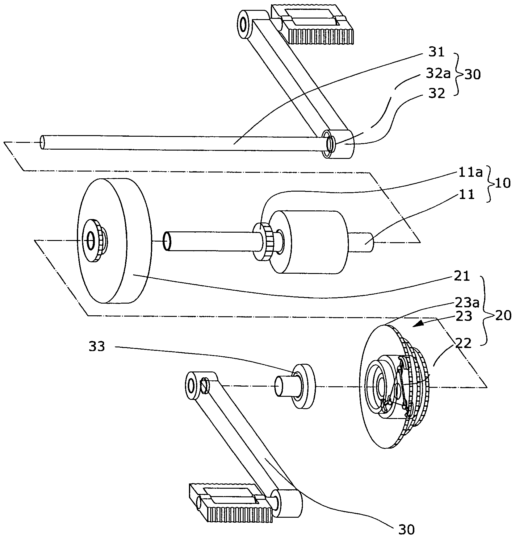
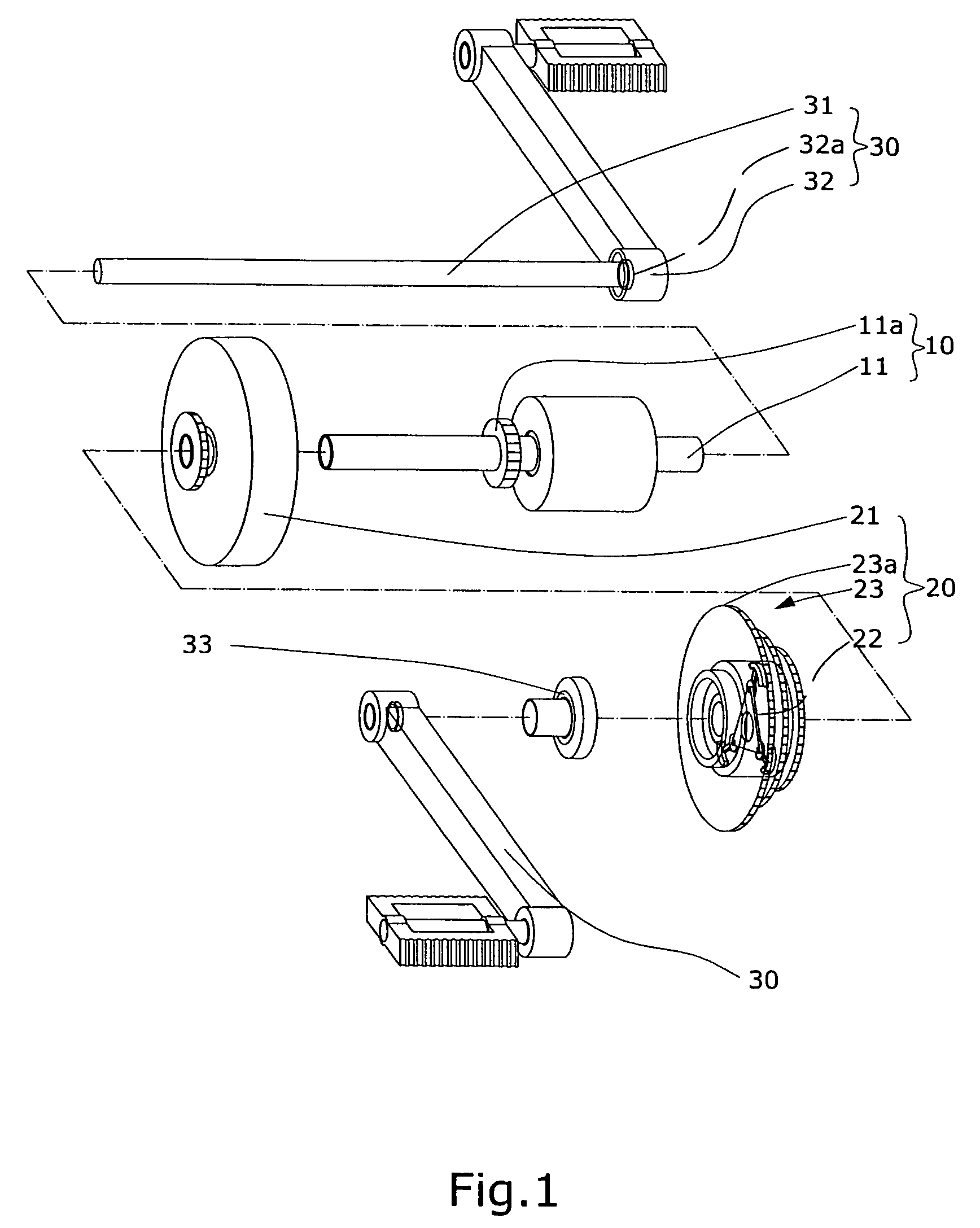
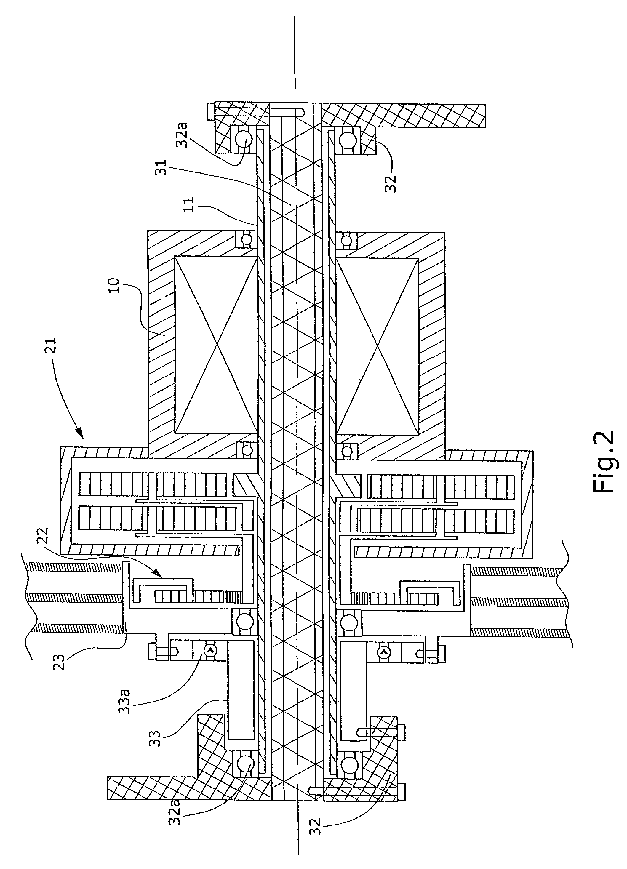
[0015]To better understand the invention, detailed descriptions of a preferred embodiment shall be given with the accompanying drawings below. Referring to FIGS. 1 and 2, an electric bicycle power structure according to the invention comprises a motor 10, a power exchange device 20 and pedal interlocking shafts 30.

[0016]The motor has a hollow tube 11 forming an axis, which is provided with a gear 11a at an appropriate position at a front end thereof.

[0017]Referring to FIGS. 3A and 3B, the power exchange device 20 has a planet decelerating mechanism 21, a clutch 22 and a chain wheel cover 23; and is disposed at a front end of the motor 10. The gear 11a at the hollow tube 11 of the motor 10 is pivotally disposed at a center of the planet decelerating mechanism 21, and is connected to an interior of the planet decelerating mechanism 21. The planet decelerating mechanism 21 has a protruding central gear 21a disposed at a front end thereof and also pivotally at a center of the clutch 22....


PUM


Abstract

An electric bicycle power structure includes a motor, a power exchange device and pedal interlocking shafts; and provides power through the motor or the pedaling pedal interlocking shafts, wherein the powerexchange device automatically switches between the motor and the pedal interlocking shafts to accomplish power saving effects. The power exchange device has a planet decelerating mechanism, a clutch and a chain wheel cover. The power exchange device is located between the motor and the pedal interlocking shaft and is capable of directly switching between these power generating devices. A chain is used to impel the gear and wheel at the chain wheel cover, and an existing transmission gear of the bicycle is employed for accomplishing transmission effects, thereby decreasing numbers of parts without changing designs of the bicycle to further reduce production costs.

Description

BACKGROUND OF THE INVENTION[0001](a) Field of the Invention[0002]The invention relates to an electric bicycle power structure, and more particularly, to an electric bicycle power structure comprising a motor, a power exchange device and pedal interlocking shafts and providing power through the motor or pedaling means, wherein the power exchange device automatically switches between power generating devices for accomplishing power savings effects.[0003](b) Description of the Prior Art[0004]Thanks to uplifting of environmental protection awareness for reducing environmental pollution, a second transportation means is commonly adopted. Using bicycles or electric bicycles as transportation means for short-distance or shopping trips is not only free from resulting in pollution, but also solves an issue as-lack of exercise of modern people. Take a prior electric bicycle for an example, an electric motor is installed at the bicycle and is for providing electric power through electric cells...

Claims


Application Information

Patent Timeline
Patent Type & Authority Patents(United States)
IPC IPC(8): B62M23/02B62M6/55
CPCB62M6/55
Inventor PERNG, TE-YU
Owner PERNG TE YU
Why Eureka
Try Eureka