Handle for doors or hinged flaps of vehicles

a technology for doors or hinged flaps and handles, which is applied in the direction of locking applications, contact mechanisms, electrical locking circuits, etc., can solve the problems of individual plastic components, unintegrated in the handles of vehicles, and the entire handle is disassembled, etc., to achieve reliable, inexpensive, and easy production

Inactive Publication Date: 2007-09-25
HUF HULSBECK & FURST GMBH & CO KG
View PDF11 Cites 31 Cited by
  • Summary
  • Abstract
  • Description
  • Claims
  • Application Information

AI Technical Summary

Benefits of technology

[0009]The objective of the invention is to develop a reliable, inexpensive handle of the aforementioned type, which can be produced quickly and easily. In accordance with the invention, essentially two assemblies are used to produce the push-button switch. There is a first assembly, which is produced as a single piece in a three-plastic-component injection-molding technique and will be referred to hereinafter simply as the “shell unit”. This shell unit consists of a nondeformable shell-like housing, an elastic membrane that seals the base of the visible end of the shell, and a nondeformable push button on the membrane at the base. The shell unit has a shell-like opening on its rear side opposite the membrane. The second assembly is preassembled from the following individual parts: a circuit board with electrical feed and conduction cables and a microswitch mounted on the circuit board. This second assembly is inserted into the interior of the shell unit and thus constitutes an “insertion unit”.

Problems solved by technology

If defects developed in the bush-button switch, it was necessary to dismount the entire handle and replace it with a new handle.
This was expensive and time-consuming.
However, these were assembled from individual plastic components and were not integrated in the handles of vehicles.
Due to the assembly of this actuator on the vehicle, the production costs are high.
A reliable seal of the installed microswitch against splashed water is not guaranteed.
The assembly of the push-button switch from its components in the handle is expensive.

Method used


Image

  • Handle for doors or hinged flaps of vehicles
  • Handle for doors or hinged flaps of vehicles
  • Handle for doors or hinged flaps of vehicles

Examples


Embodiment Construction

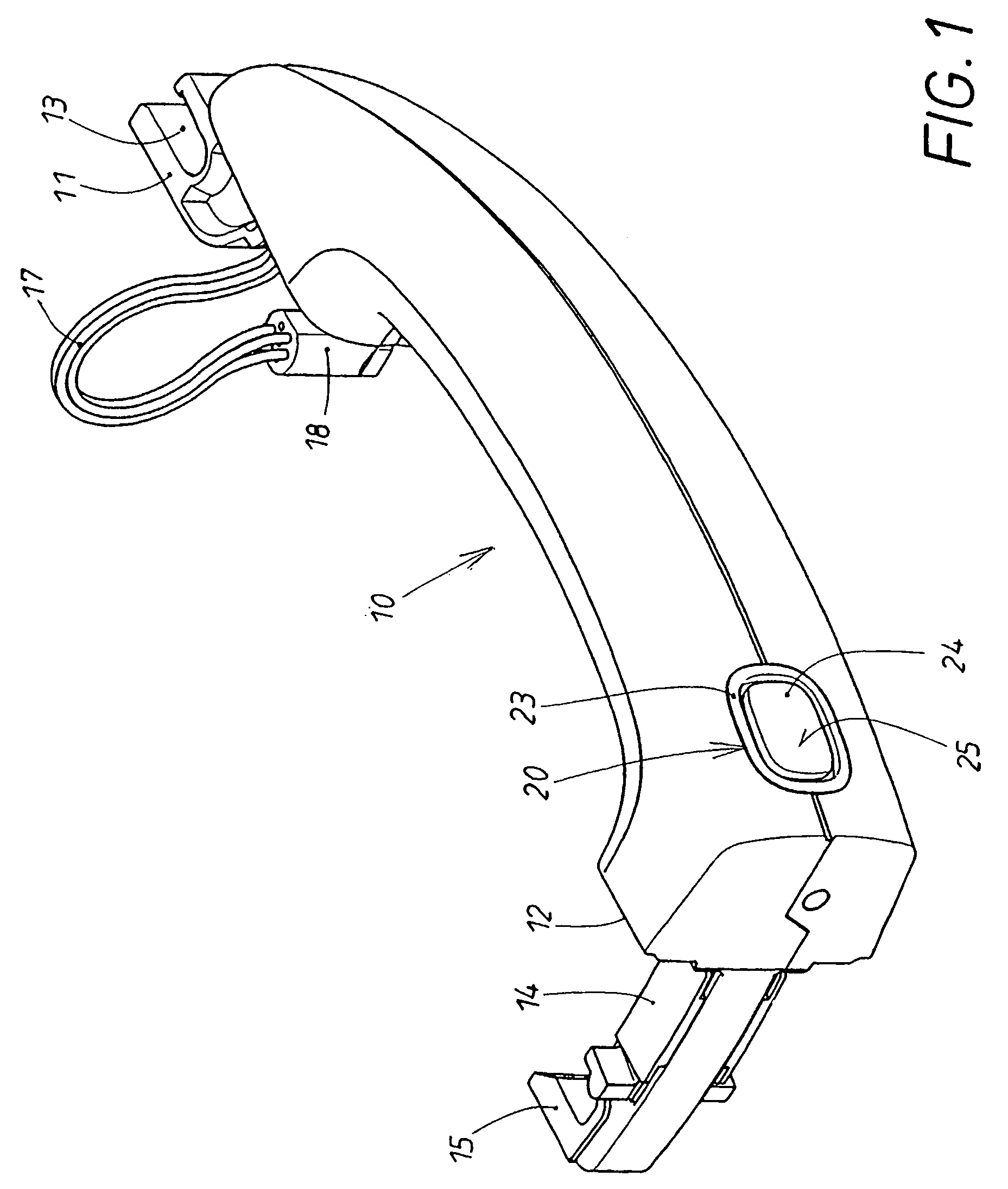
[0022]One end 11 of the handle 10 of the invention has a bearing receptacle 13, about which the handle 10 can be manually turned when it is mounted in a door or hinged lid. At the other end 12 of the handle 10, there is a shaft 14, which engages the inside of the door and has a terminal hooked head 15, which acts on a lock located inside the door during the aforesaid turning movement of the handle 10. This operation is normally carried out to open the door when the lock is unlocked. The lock is part of a complex locking system.

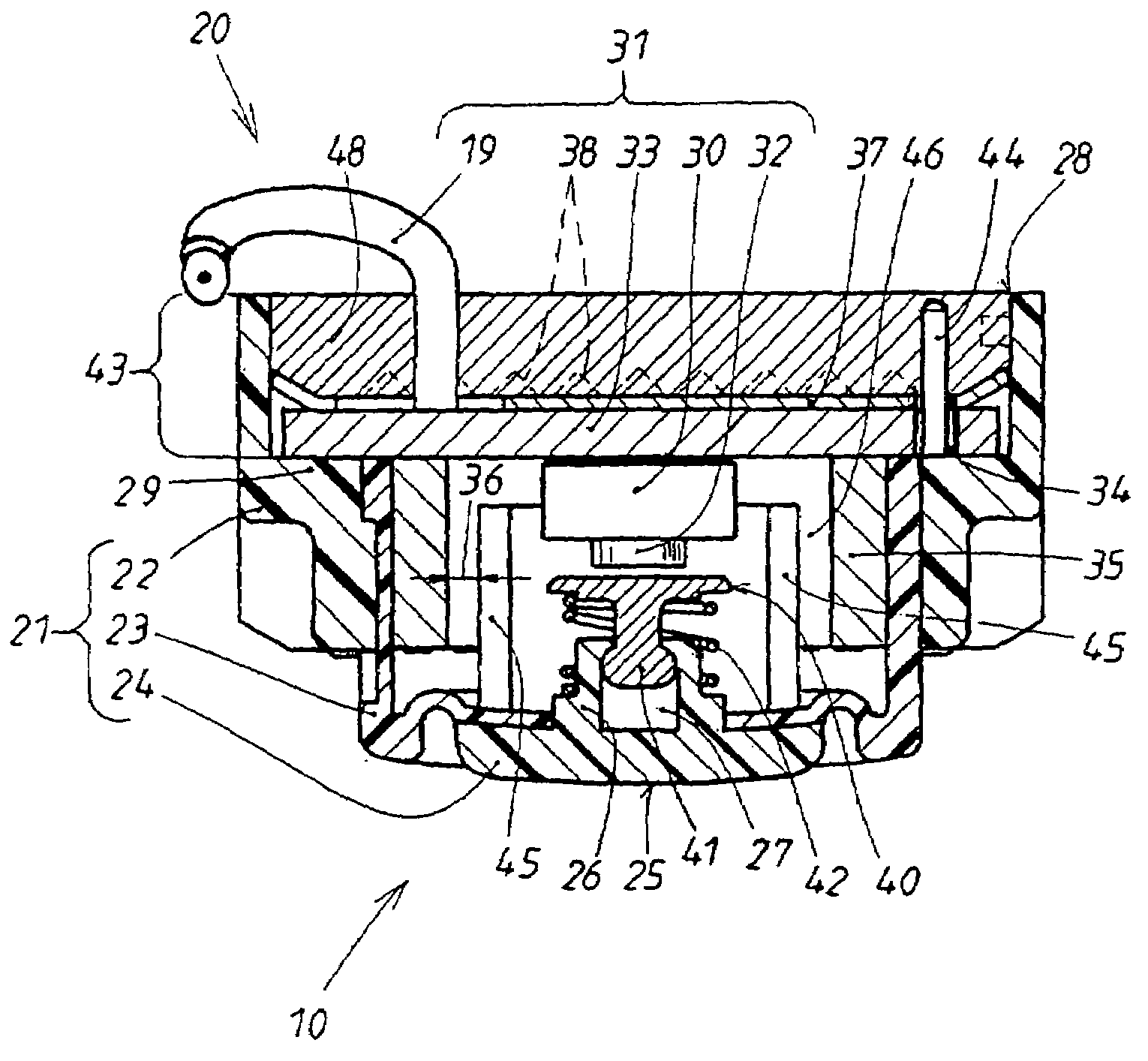
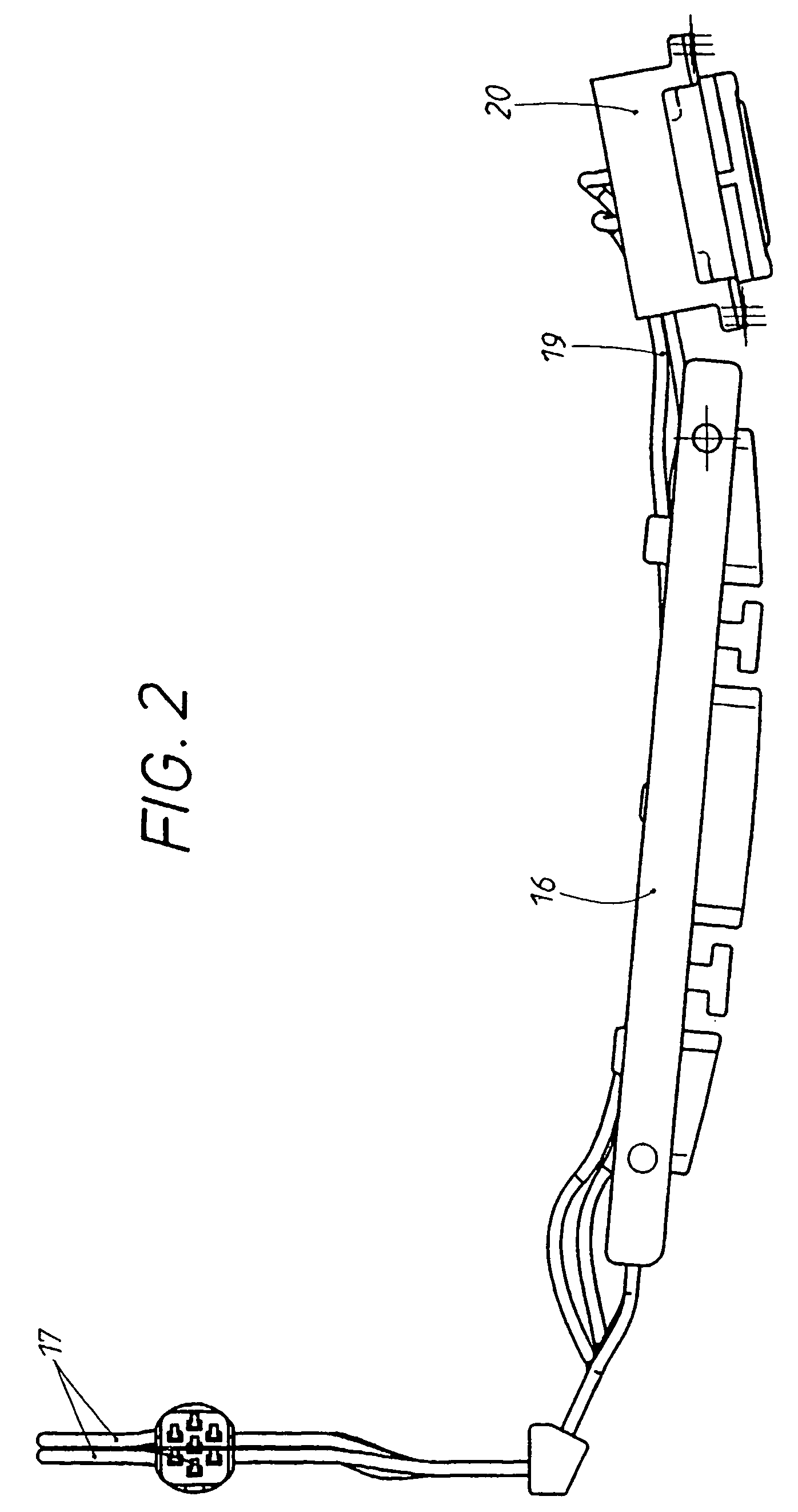
[0023]This locking system also includes a proximity sensor, which is integrated in the interior of the hollow handle 10. The proximity sensor 16 is shown in the unmounted state in FIG. 2 and is activated, normally by capacitance, when the hand approaches the handle 10. The generation and conduction of the sensor signals occurs via electrical cables 17, which, as shown in FIG. 1, emerge at the supported end 11 of the handle and end in an electrical coupling, su...


PUM


Abstract

The invention relates to a handle with an integrated switch (20) for doors or hinged flaps of vehicles. The push-button switch is essentially made up of two components which can be fitted together. The first component (21) is made of a single-pieced injection-moulding product made of three plastic components which comprise a solid covering-shaped housing and an elastic membrane. Said membrane closes the housing cover (22) at the base on one end thereof, thus giving the component (21) a shell shape. A solid pressure activator (24) on the membrane (23) is used as the third plastic component. The second component (31) is formed from a circuit board (33) comprising connected cables (19) and a microswitch (30) mounted thereon. The second component (31) is inserted into the inside of a shell (26) of the first component (21). The circuit board (33) is oriented towards the shell opening (28) and is projected from the edge of the shell (43) of the shell-shaped component (21). Said connecting area of both components (21, 31) is secured by a safety plate (37) which covers at least the inserted circuit board (33) in certain areas. The remaining part of the shell edge of the shell-shaped component (21) is used as a mould and becomes a sealing compound (48) which closes the shell opening (28) after hardening.

Description

BACKGROUND OF THE INVENTION[0001]1. Field of the Invention[0002]The invention concerns a handle with a built-in push-button switch. If the handle and / or the push-button switch is manually operated, a locking system in the vehicle is acted upon, which serves to lock, unlock, open, and / or close a lock in the door or hinged lid. Besides the push-button switch, the handle accommodates other electric or electronic components, such as a capacitance sensor, which already responds when a hand approaches the handle and acts on the locking system.[0003]2. Description of the Related Art[0004]In the previously known handle of this type (DE 196 17 038 C2), the push-button switch and the electronic components were sealed inside the handle after they had been installed. If defects developed in the bush-button switch, it was necessary to dismount the entire handle and replace it with a new handle. This was expensive and time-consuming.[0005]Electromechanical push-button switches with a housing, an ...

Claims


Application Information

Patent Timeline
Patent Type & Authority Patents(United States)
IPC IPC(8): H01H9/00E05B65/20E05B65/26H01H13/06H01H13/08H01H13/20
CPCE05B81/76E05B85/16H01H13/06H01H13/08H01H13/20H01H2221/064E05B79/06E05B85/10
Inventor KORULTAY, ERKANKILIAN, MARION
Owner HUF HULSBECK & FURST GMBH & CO KG
Why Eureka
Try Eureka