System and method for defining T-spline and T-NURCC surfaces using local refinements

a local refinement and surface technology, applied in the field of defining a modeled surface, can solve the problems of increasing the modeling complexity of the surface, unable to allow uniform b-spline surfaces, and non-uniform b-spline surfaces

Active Publication Date: 2007-09-25
AUTODESK INC
View PDF7 Cites 17 Cited by
  • Summary
  • Abstract
  • Description
  • Claims
  • Application Information

AI Technical Summary

Benefits of technology

[0019]A system and method is provided for creating a bi-cubic spline surface in a computing environment. One operation in the method is defining a control mesh with a substantially rectangular structure. A further operation is inferring from the control mesh the tensor product B-spline basis functions for each control point. The surface can then be computed based on the basis functions and the control mesh.

Problems solved by technology

A drawback of polygonal meshes is that they are inherently faceted, and a large number of polygons may be needed to make the facets small enough to satisfy the demands of the application.
Unfortunately, adding an entire row of control points for each desired new control point simply to satisfy the rectangular grid topology of NURBS surfaces increases the modeling complexity of the surface dramatically.
Uniform B-spline surfaces do not allow arbitrary knot insertion, for as soon as a single knot is inserted, the surface becomes a non-uniform B-spline surface.
Since uniform B-splines cannot support two or more identical knots, uniform B-spline surfaces are always Cn−1 continuous and it is not possible to impose a C0 crease.
The problem is to minimize the number of knots subject to an error tolerance.
The presence of such gaps places a burden on modelers who potentially must repair a widened gap whenever the model is deformed.
A second reason why this constraint is so serious is because it typically means that a large number of NURBS control points serve no purpose other than to satisfy topological constraints.
Superfluous control points are a serious nuisance for designers, not merely because they require the designer to deal with more data, but also because they can introduce unwanted ripples in the surface. FIG. 1 shows a NURBS head model.
Designers can waste dozens of hours on models, such as FIG. 1, in tweaking the NURBS control points while attempting to remove unwanted ripples.
A third reason why the rectangular grid constraint is a problem is that it is not possible to insert a single control point into a NURBS control grid, but rather, an entire row of control points must be added each time a single knot insertion is performed.
This means that true local refinement of NURBS surfaces is not possible, since the insertion of a single control point demands the insertion of an entire row into the control grid.
Particularly, the notion of T-splines presented in the Bakenov thesis contains limitations that render it almost useless.
Most significantly, the T-splines described in the Bakenov thesis are not capable of solving the problems associated with NURBS without the solution of a potentially huge system of linear equations, for which a solution does not exist in many cases.
For these reasons, the notion of T-splines contained in the Bakenov thesis is of little practical value.
A problem with Catmull-Clark surfaces is that, since they are based on uniform B-spline surfaces, it is not possible to represent sharp C0 features.
Another more serious problem is that local refinement of Catmull-Clark surfaces is not possible.

Method used


Image

  • System and method for defining T-spline and T-NURCC surfaces using local refinements
  • System and method for defining T-spline and T-NURCC surfaces using local refinements
  • System and method for defining T-spline and T-NURCC surfaces using local refinements

Examples


Embodiment Construction

[0047]Reference will now be made to the exemplary embodiments illustrated in the drawings, and specific language will be used herein to describe the same. It will nevertheless be understood that no limitation of the scope of the invention is thereby intended. Alterations and further modifications of the inventive features illustrated herein, and additional applications of the principles of the inventions as illustrated herein, which would occur to one skilled in the relevant art and having possession of this disclosure, are to be considered within the scope of the invention.

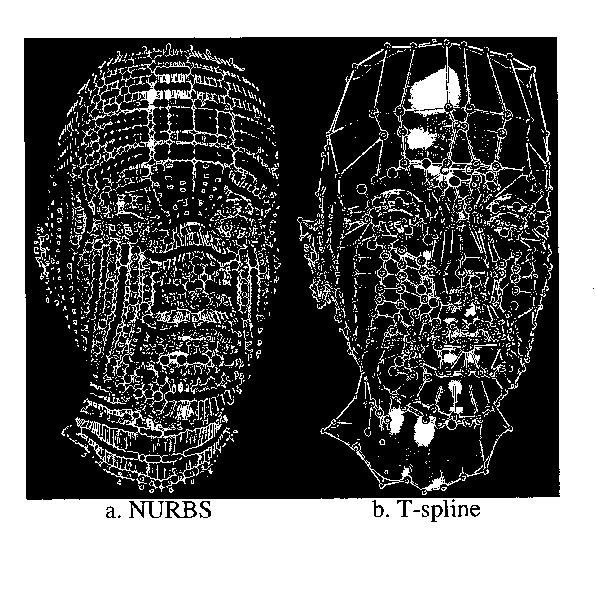
[0048]The present system and method of the invention provide a generalization and improvement of non-uniform B-spline surfaces (NURBS) called T-splines. A major problem with NURBS surfaces is that, because NURBS control points must lie topologically in a rectangular grid, it is often the case that a large percentage of the NURBS control points serve no purpose other than to satisfy the rectangular grid topology. ...


PUM


Abstract

A system and method is provided for defining a bi-cubic spline surface in a computing environment. One operation in the method is creating a control mesh with a substantially rectangular structure. A further operation is inferring from the control mesh the tensor product B-spline basis functions for each control point. The surface can then be computed based on the basis functions and the control mesh.

Description

[0001]The patent application claims priority to U.S. Provisional Patent Application No. 60 / 458,231, entitled “T-splines” and filed on Mar. 26, 2003.FIELD OF THE INVENTION[0002]The present invention relates generally to defining a modeled surface that is capable of expressing local refinements.BACKGROUND[0003]Surface modeling is a fundamental task in computer graphics, computer aided design (CAD), computer aided geometric design (CAGD), and computer animation. Surfaces are typically approximated by a mesh of polygons or piecewise polynomial patches. Because of their simplicity, polygonal meshes are a popular way to approximate surfaces and are adequate for many applications. A drawback of polygonal meshes is that they are inherently faceted, and a large number of polygons may be needed to make the facets small enough to satisfy the demands of the application.[0004]In contrast, a popular smooth surface representation is tensor product B-spline surfaces. The control points for a B-spli...

Claims


Application Information

Patent Timeline
Patent Type & Authority Patents(United States)
IPC IPC(8): G06T17/00G06FG06F1/00G06F17/00G06F17/50G06T17/20
CPCG06F17/50G06T17/20G06F30/00G06F17/00
Inventor SEDERBERG, THOMAS W.
Owner AUTODESK INC
Why Eureka
Try Eureka