Touch sensor type liquid crystal display having a plurality of spacers, each comprising two members adapted to slide relative to each other in response to a contact force

Inactive Publication Date: 2007-09-25
IBM CORP
View PDF5 Cites 44 Cited by
  • Summary
  • Abstract
  • Description
  • Claims
  • Application Information

AI Technical Summary

Benefits of technology

[0021]The regular arrangement of the spacers is advantageous in various respects for the touch sensor type liquid crystal display. For example, arrangement of the spacers keeps constant the amount of bending caused by touching the touch sensor panel in any position in the planar direction of the liquid crystal display panel. Accordingly, uneven bending of the liquid crystal display panel can be prevented.
[0022]According to the present invention, the regular arrangement of the gap controlling spacers in the planar direction of the liquid crystal display panel means not only a

Problems solved by technology

Also, because of the structure permitting movement of the spacers in the liquid crystal layer, the display electrode formed on the surface of the color filter substrat

Method used


Image

  • Touch sensor type liquid crystal display having a plurality of spacers, each comprising two members adapted to slide relative to each other in response to a contact force
  • Touch sensor type liquid crystal display having a plurality of spacers, each comprising two members adapted to slide relative to each other in response to a contact force
  • Touch sensor type liquid crystal display having a plurality of spacers, each comprising two members adapted to slide relative to each other in response to a contact force

Examples


second embodiment

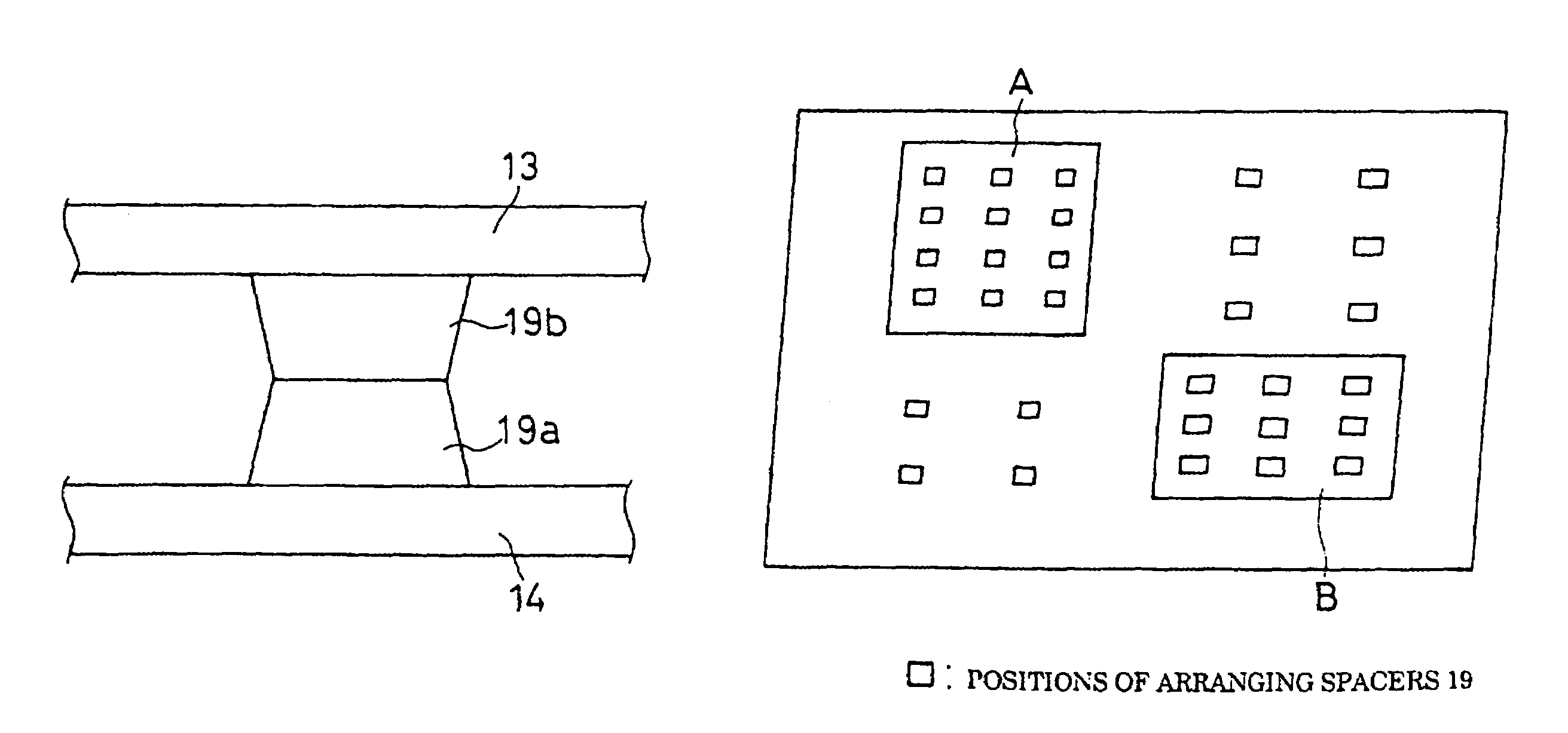
[0076]With the touch sensor type liquid crystal display 1 of the second embodiment, as shown in FIG. 10, a density of spacers 19 is higher toward a center of the liquid crystal display panel 2 (only a part is shown). There is a structural reason for this higher density. Specifically, the amount of bending is larger toward the center of the liquid crystal display panel when the touch sensor is touched and, hence, to deal with the bending, more spacers 19 are disposed in the center having a larger bending amount.

[0077]Other constitutional elements and a manufacturing method of the second embodiment are the same as those of the first embodiment, and thus description thereof will be omitted.

[0078]In the first and second embodiments that have been described, the liquid crystal material is driven by using the thin film transistor based on the active matrix system. Driving can also be performed by using other systems such as a direct driving system and a beam address system. Color displayi...

first embodiment

[0079]In the first embodiment, the PET film is used for the fixed electrode plate 4. Glass can be used instead, depending on a specific purpose. In the case of using the glass, however, weight-reduction and thinning of the touch sensor type liquid crystal display may not be sufficient. Thus, a flexible material such as a PET film should preferably be used.

[0080]The spacers 19 are formed on the array substrate 14 in the first embodiment, and the spacers 19 are formed on the color filter substrate 13 in the second embodiment. But spacers 19 can be formed on both sides of the array and color filter substrates 14 and 13. In this case, care must be taken to make a sum total of heights of the spacers formed on the array and color filter substrates 14 and 13 coincident with a gap, i.e., a cell gap, between these substrates. For example, as shown in FIG. 11, each height of spacers 19a and 19b respectively formed on the array and color filter substrates 14 and 13 is set to be ½ of a cell gap...


PUM


Abstract

A touch sensor type liquid crystal display is disclosed to provide a touch sensor type liquid crystal display which can endure long-time use while achieving a weight reduction. The touch sensor type liquid crystal display includes: a liquid crystal display panel 2 having an array substrate 14 and a color filter substrate 13, which are arranged oppositely to each other by interpolating a liquid crystal layer 18; and a touch sensor panel 3 having a movable electrode plate 4 and a fixed electrode plate 5, which are arranged oppositely to each other by a specified gap. These panels 2 and 3 are laminated together. A gap controlling spacer 19 is fixed in the array substrate 14 to restrict a spacer movement in a planar direction.

Description

BACKGROUND OF THE INVENTION[0001]1. Field of the Invention[0002]The present invention relates to a touch sensor type liquid crystal display equipped with a touch sensor function on a liquid crystal display panel, and more particularly to a liquid crystal display with a resistive membrane touch sensor.[0003]2. Description of the Related Art[0004]Resistive touch membrane sensors are employed to provide a way to input or select information displayed on a display device. Referring to FIG. 13, an example of a conventional resistive membrane touch sensor type liquid crystal display is shown, which was disclosed in Japanese Patent Laid-Open Hei 7 (1995)-84705. In the present specification, a touch sensor type liquid crystal display means one having a touch sensor function added to a liquid crystal display panel, whatever mode may be employed.[0005]As shown in FIG. 13, this touch sensor type liquid crystal display 1 includes a touch sensor panel 3 laminated on a liquid crystal display panel...

Claims


Application Information

Patent Timeline
IPC IPC(8): G02F1/1339G06F3/041G02F1/1333G06F3/03
CPCG02F1/13338G02F1/13394G06F3/0412G06F3/045G06F2203/04103
Inventor KURIHARA, MIKIOKANZAKI, EISUKE
Owner IBM CORP
Why Eureka
Try Eureka