Light-emitting textile structure, in particular for medical purposes, and use thereof

a textile structure and light-emitting technology, applied in the field of light-emitting textile structure, can solve the problems of difficult realization of woven textile structure, difficult to realize with woven textile structure, and many applications, and achieve the effect of great flexibility

Inactive Publication Date: 2007-09-25
BIOLITEC UNTERNEHMENSBETEILLIGUNGS II AG
View PDF7 Cites 34 Cited by
  • Summary
  • Abstract
  • Description
  • Claims
  • Application Information

AI Technical Summary

Benefits of technology

[0010]Furthermore, the light emission distribution can be changed without need for any changes of the textile structure simply by varying the intensity of the light that is coupled into the individual fibers. Any individual light-emitting element is formed by one or preferably by several output zones, each of which is formed by a local curvature of the optical fiber, the local curvature being selected in such a way that due to the absence of total reflection there is a lateral exit of light from the fiber, i.e. from its external surface. In this way the individual light-emitting elements can be designed in a very compact manner, thus permitting a large number of light-emitting elements per unit area and thus allowing for good control of the light emission distribution of the textile structure. Because the individual light-emitting elements are functional units that are independent of each other, a light-emitting textile structure with very high flexibility can be produced by means of an appropriately designed support. Therefore, the light-emitting textile structure of the present invention is not only useful for illumination of flat objects, but also for the illumination of structured objects. For example, in medical treatment it can be used like a conventional textile structure on the skin and for other internal and external organs of the body.
[0011]With appropriate manufacturing conditions, the light-emitting textile structure of the present invention can be produced very economically and is, therefore, also useful for once-only use, i.e. as a disposable item.
[0013]A particular use of the textile structure is defined in claim 15. Thereby, at least one output zone of an optical fiber is used as light collector in order to lead light impinging onto the textile structure away through the optical fiber. For example, this allows determining—continuously or from time to time—the fluorescence intensity of an irradiated object, in particular of an irradiated tissue region. In this way, photodynamic diagnosis can be performed in situ, thus offering significant advantages in comparison with conventional methods.
[0016]In principle, there are various possibilities for fixing the light-emitting elements to the support. Advantageously, the light-emitting elements are stitched to the support according to claim 3. In this way, it is possible to achieve a well-defined arrangement of the individual light-emitting elements at the intended positions on the support while nonetheless having a rather loose arrangement of the supplying optical fibers. The result is a light-emitting textile structure having great flexibility.

Problems solved by technology

An important disadvantage of this type of arrangement is caused by the fact that the light emission intensity of the individual light-emitting elements decreases along the fiber.
However, this is a demanding task, which is particularly difficult to realize with a woven-type textile structure, which as a rule is built up periodically.
This, however, is against the requirements of many applications, particularly many medical applications that require that the illumination of an area to be irradiated with light be as uniform as possible.
The arrangement of light-emitting elements in a pearl string fashion according to EP 0 359 450 A2 is also not useful for applications in which an illumination with a predefined inhomogeneity is specifically required.
Again, the sequential arrangement of light-emitting elements turns out to be a substantial limitation, as the intensity distribution along a chain of light-emitting elements is substantially predefined, i.e. it is merely possible to arbitrarily vary the intensity in transverse direction with respect to the optical fibers by specifically providing the various fibers with light of differing intensity.
In longitudinal direction, however, no variation of intensity is possible for a given arrangement of the woven fabric.
Importantly, the lateral exit of light is not achieved necessarily by wavy optical fibers.
Again, a lateral emission of light out of the optical fibers is achieved by local damages, particularly scratches.
Although this solution allows for an approximately homogeneous distribution of light emission across the entire light-emitting woven fabric, there is no possibility to generate an inhomogeneous distribution of a given shape in warp direction once the woven fabric is finished.
The problem of intensity decrease along the fibers is not mentioned; however, the provision of a homogeneously fluorescing textile structure is just not the aim of U.S. Pat. No. 4,727,603.
On the other hand, the non-homogeneous distribution of light emission is predetermined by means of the stitching pattern, and a subsequent modification thereof is either not possible or is possible only to a limited amount.

Method used


Image

  • Light-emitting textile structure, in particular for medical purposes, and use thereof
  • Light-emitting textile structure, in particular for medical purposes, and use thereof
  • Light-emitting textile structure, in particular for medical purposes, and use thereof

Examples


examples

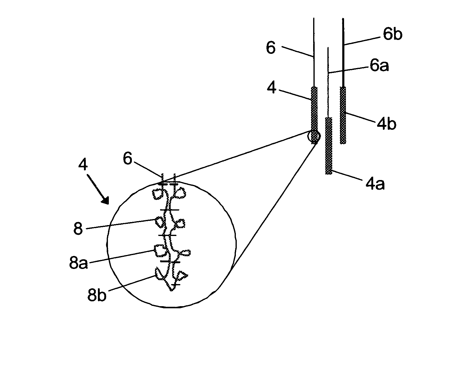
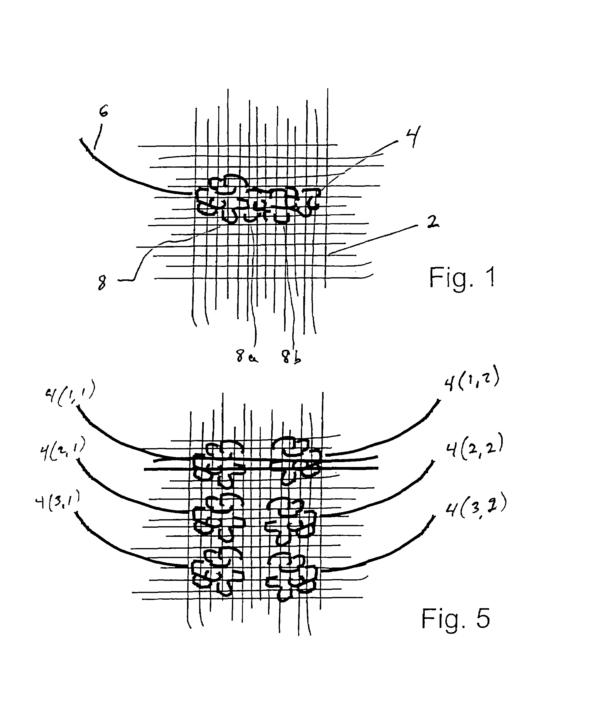
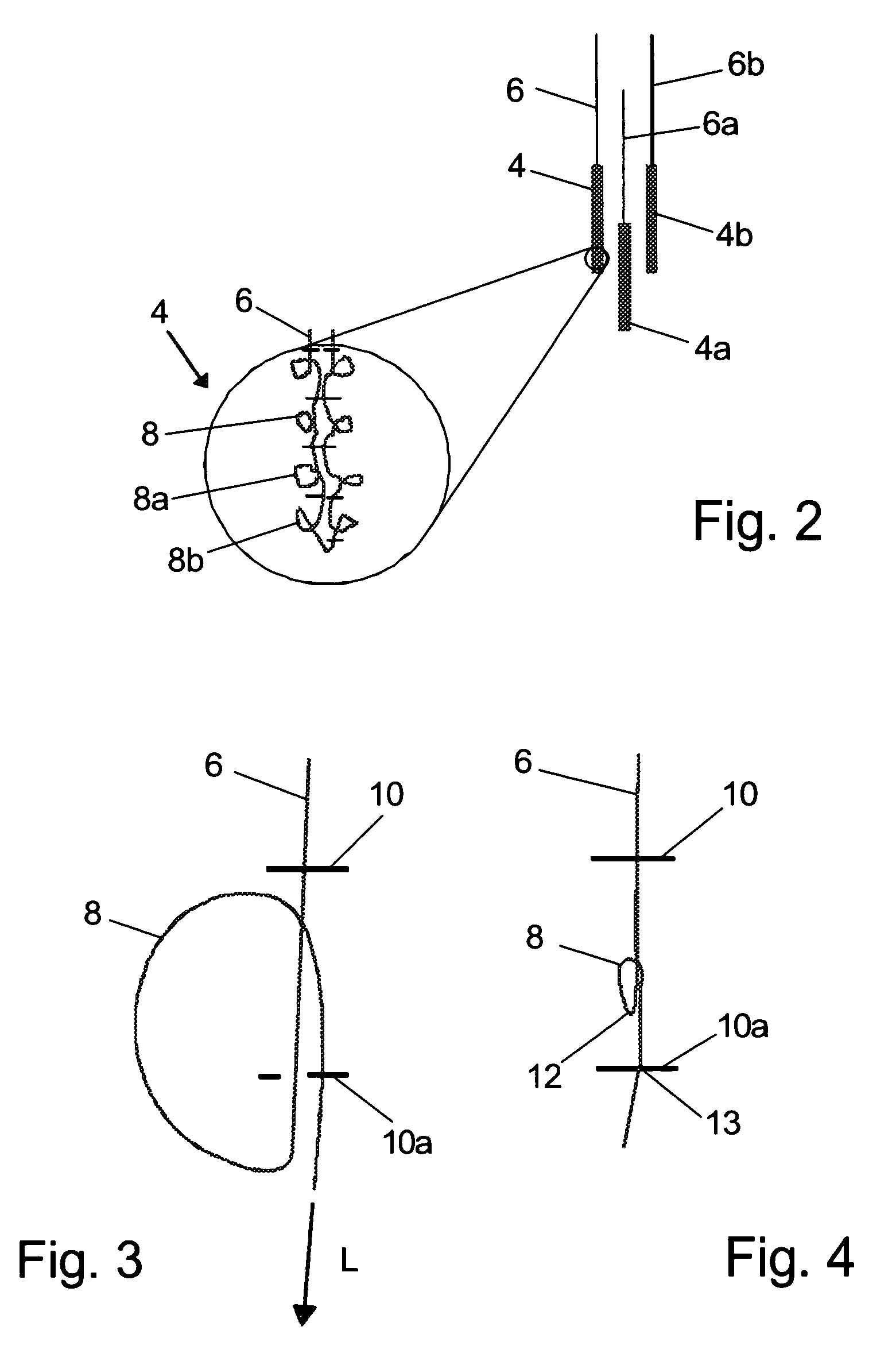
[0038]FIG. 1 shows a section of a light-emitting textile structure that comprises a flat support 2 onto which is affixed a light-emitting element 4 with a light-supplying optical fiber 6. The light-emitting element 4 comprises a number of loops 8, 8a, 8b, etc., the curvature of which is selected in such a way that a lateral exit of light from the optical fiber 6 occurs due to the absence of total reflection. Therefore, the above-mentioned loops act as output zones. It should be noted that the light-emitting element shown in FIG. 1 is formed from a single optical fiber, and for reasons of drawing only the parts of the fiber 6 that lie above the drawing plane are shown. The light-emitting elements can be attached to just one side or to both sides of support 2 depending on what type of application the textile structure is intended for.

[0039]In its entirety, the light-emitting textile structure comprises a plurality of light-emitting elements with associated optical fibers, with exactly...


PUM


Abstract

A light-emitting textile structure, which in particular is useful for medical purposes, comprises a flat support (2) and a plurality of light-emitting elements (4) fixed thereto. Each light-emitting element comprises a light-supplying optical fiber (6), to each optical fiber (6) there being associated exactly one light-emitting element (4), which comprises at least one output zone formed by a local curvature of the optical fiber. The local curvature is selected in such a way that a lateral exit of light from the optical fiber occurs due to the absence of total reflection.

Description

FIELD OF THE INVENTION[0001]The invention relates to a light-emitting textile structure according to the preamble of claim 1 and to a use thereof.PRIOR ART[0002]A related textile structure is disclosed in EP 0 359 450 A2. The textile structure described therein is designed as a light-emitting plate having at one side thereof a plurality of woven optical fibers provided with bends at discrete locations along the length of the fibers. These bends have the effect that light guided within the fibers is laterally emitted from the optical fibers at the bend zones due to the absence of total reflection. As possible uses of the light-emitting plate, there are described, amongst others, phototherapeutic treatments, for example the phototherapy of jaundice in newborns.[0003]The known light-emitting textile structure is made in the way of a woven fabric in which the light guiding fibers are arranged as warp threads and the bends acting as light-emitting elements are situated at the intersectio...

Claims


Application Information

Patent Timeline
Patent Type & Authority Patents(United States)
IPC IPC(8): G02B6/26F21V21/08
CPCA61B5/6804A61N5/062A61N5/0624G02B6/001A61B5/0059A61N5/0616A61N5/0621A61N2005/063A61N2005/0645
Inventor WALT, HEINRICHSELM, BARBELWESSEL, THOMAS
Owner BIOLITEC UNTERNEHMENSBETEILLIGUNGS II AG
Why Eureka
Try Eureka