Micro-electro-mechanical sensor with force feedback loop

a micro-electromechanical and sensor technology, applied in the direction of acceleration measurement using interia force, speed measurement using gyroscopic effects, electric/magnetic means, etc., can solve the problems of complex production of available reading devices for mems, cumbersome and, in practice, costly

Active Publication Date: 2007-10-02
STMICROELECTRONICS SRL
View PDF16 Cites 45 Cited by
  • Summary
  • Abstract
  • Description
  • Claims
  • Application Information

AI Technical Summary

Problems solved by technology

Hence, currently available reading devices for MEMS are complex to produce, cumbersome and, in practice, costly.

Method used


Image

  • Micro-electro-mechanical sensor with force feedback loop
  • Micro-electro-mechanical sensor with force feedback loop
  • Micro-electro-mechanical sensor with force feedback loop

Examples


Embodiment Construction

[0022]In the ensuing description, reference will be made to the use of the invention in a micro-integrated gyroscope. This must not, however, be considered as in any way limiting the scope of the invention, in so far as the latter can be exploited in all the cases where, in a micro-electro-mechanical structure, a movable mass must be excited and continuously maintained in oscillation at a natural resonance frequency. In particular, the invention can advantageously be applied to the construction of MEMS oscillators.

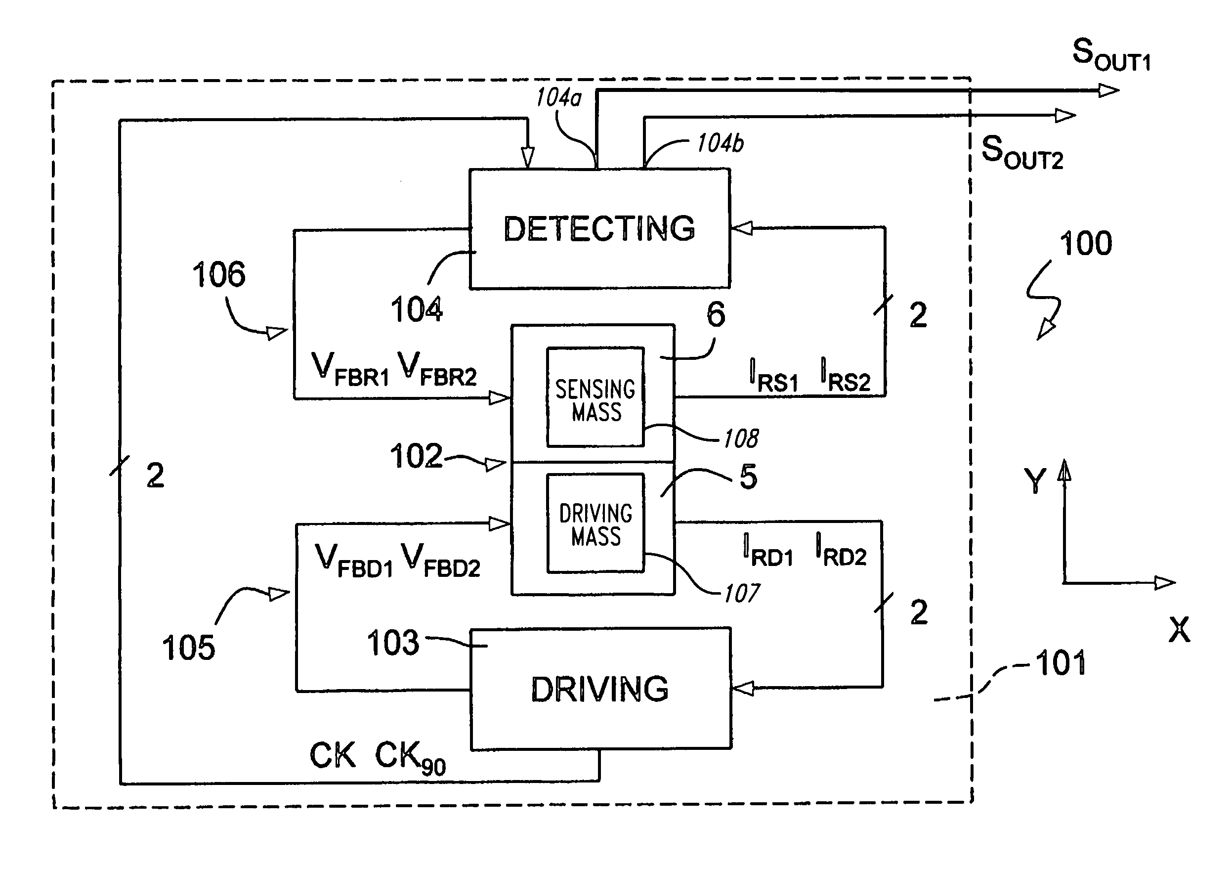
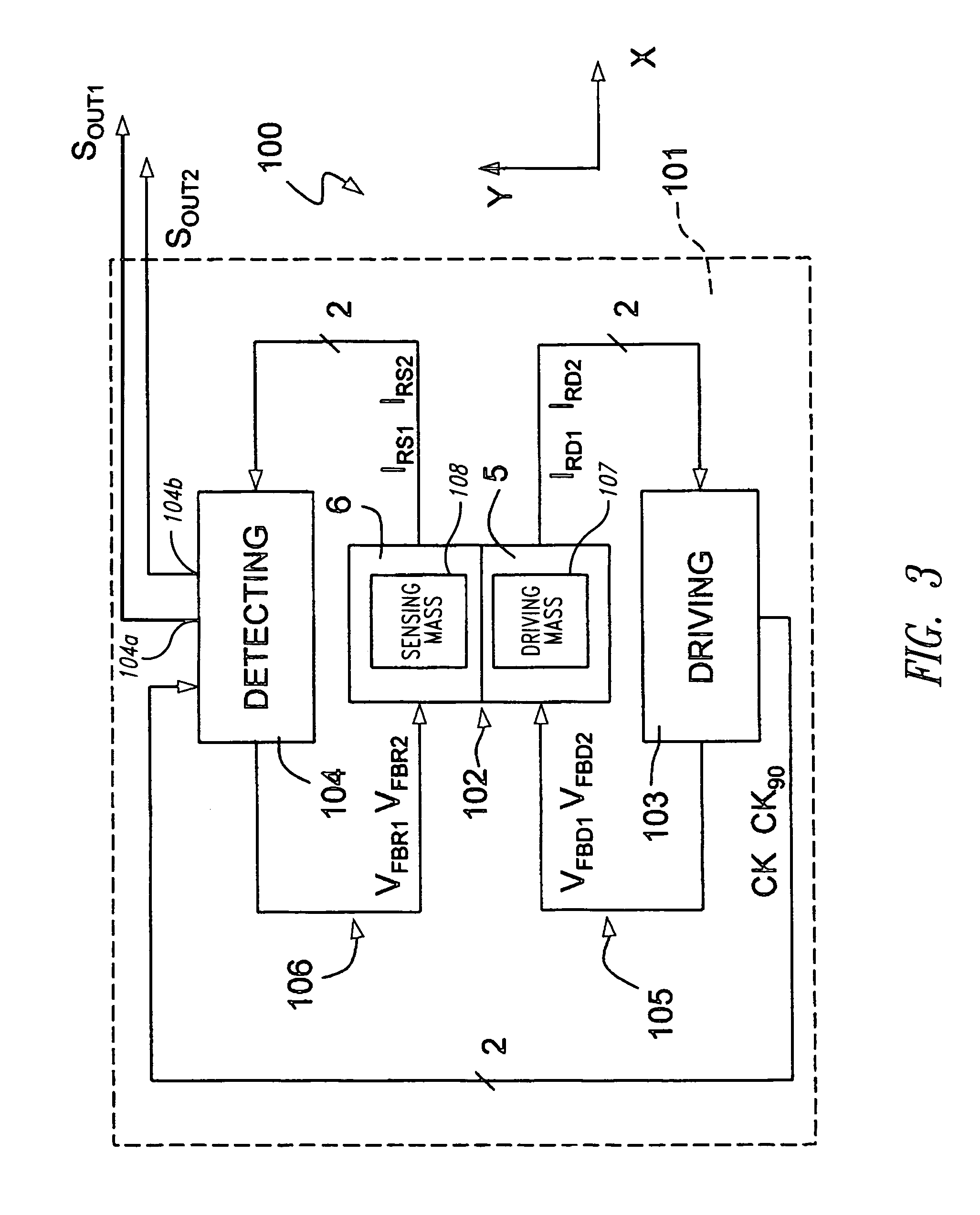
[0023]With reference to FIG. 3, a micro-integrated gyroscope 100 comprises a microstructure 102 made using MEMS technology, a driving device 103, and a reading device 104 (also referred to as a detecting device), housed on a support 101. The microstructure 102, which will be illustrated in detail hereinafter, is provided with an actuation system 5 and an inertial sensor 6, which include respective movable masses. More precisely, the actuation system 5 comprises a driving m...


PUM


Abstract

A micro-electro-mechanical sensor includes a microstructure having a mass which is movable with respect to a rest position, according to a predetermined degree of freedom, and a displacement-detecting device for detecting a displacement of the mass according to the predetermined degree of freedom. The displacement-detecting device includes a force feedback loop of a purely analog type, which supplies electrostatic forces tending to restore the mass to the rest position in response to a displacement of the mass according to the predetermined degree of freedom.

Description

BACKGROUND OF THE INVENTION[0001]1. Field of the Invention[0002]The present invention relates to a micro-electro-mechanical sensor with force feedback loop.[0003]2. Description of the Related Art[0004]As is known, the use of micro-electro-mechanical systems or MEMS is increasingly widespread in various sectors of technology and has yielded encouraging results especially in the construction of inertial sensors, micro-integrated gyroscopes, and electromechanical oscillators for a wide range of applications.[0005]MEMS systems of this type are usually based upon micro-electro-mechanical structures comprising at least one mass, which is connected to a fixed body (stator) by means of springs and is movable with respect to the stator according to predetermined degrees of freedom. The movable mass and the stator are capacitively coupled by means of a plurality of respective comb-fingered electrodes set facing one another, so as to form capacitors. The movement of the movable mass with respe...

Claims


Application Information

Patent Timeline
Patent Type & Authority Patents(United States)
IPC IPC(8): G01P15/00G01C19/56G01C19/5726
CPCG01C19/5726
Inventor CAMINADA, CARLOLASALANDRA, ERNESTOPRANDI, LUCIANO
Owner STMICROELECTRONICS SRL
Why Eureka
Try Eureka