
Differential scanning calorimeter with a second heater

a technology of calorimeter and heater, which is applied in the direction of calorimeter, material thermal analysis, instruments, etc., can solve the problems of not remarkably large power required for the first heater to increase the temperature of the heatsink, and the difficulty of heat flow to the cooling mechanism from the heatsink

Inactive Publication Date: 2007-10-02
HITACHI HIGH TECH SCI CORP
View PDF17 Cites 4 Cited by
  • Summary
  • Abstract
  • Description
  • Claims
  • Application Information

AI Technical Summary

Benefits of technology

The invention is a differential scanning calorimeter that has a heatsink for housing a measurement sample and a reference material, a first heater for heating the heatsink, and a differential heat flow detector fixed to a bottom plate of the heatsink. A cooling mechanism is provided for cooling the heatsink, and a thermoconductor equipped with a second heater is disposed between the heatsink and the cooling mechanism so that a heat path is then formed between the heatsink and the cooling mechanism by the thermoconductor. The second heater is fixed to the thermoconductor. The supply of heater power to the second heater is outputted using a preset heater power table according to the temperature and heating speed of the temperature program rather than according to feedback control. This results in a stable upper limit measuring temperature and reduces the power required for the first heater to increase the temperature of the heatsink.

Problems solved by technology

As a result, it is difficult for heat to flow to the cooling mechanism from the heatsink and the power required for the first heater to increase the temperature of the heatsink is not remarkably larger.

Method used


Image

  • Differential scanning calorimeter with a second heater
  • Differential scanning calorimeter with a second heater
  • Differential scanning calorimeter with a second heater

Examples


Embodiment Construction

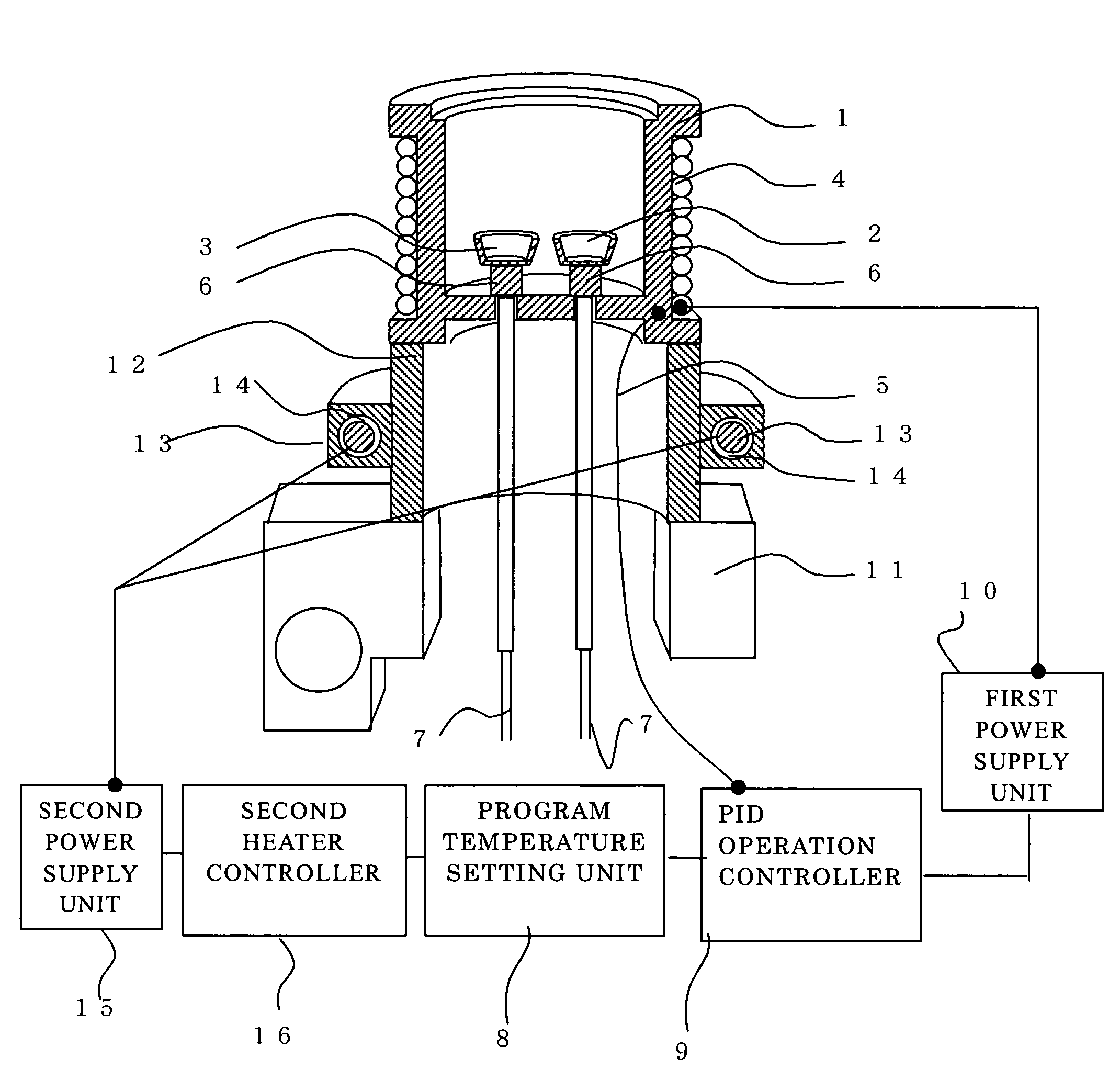
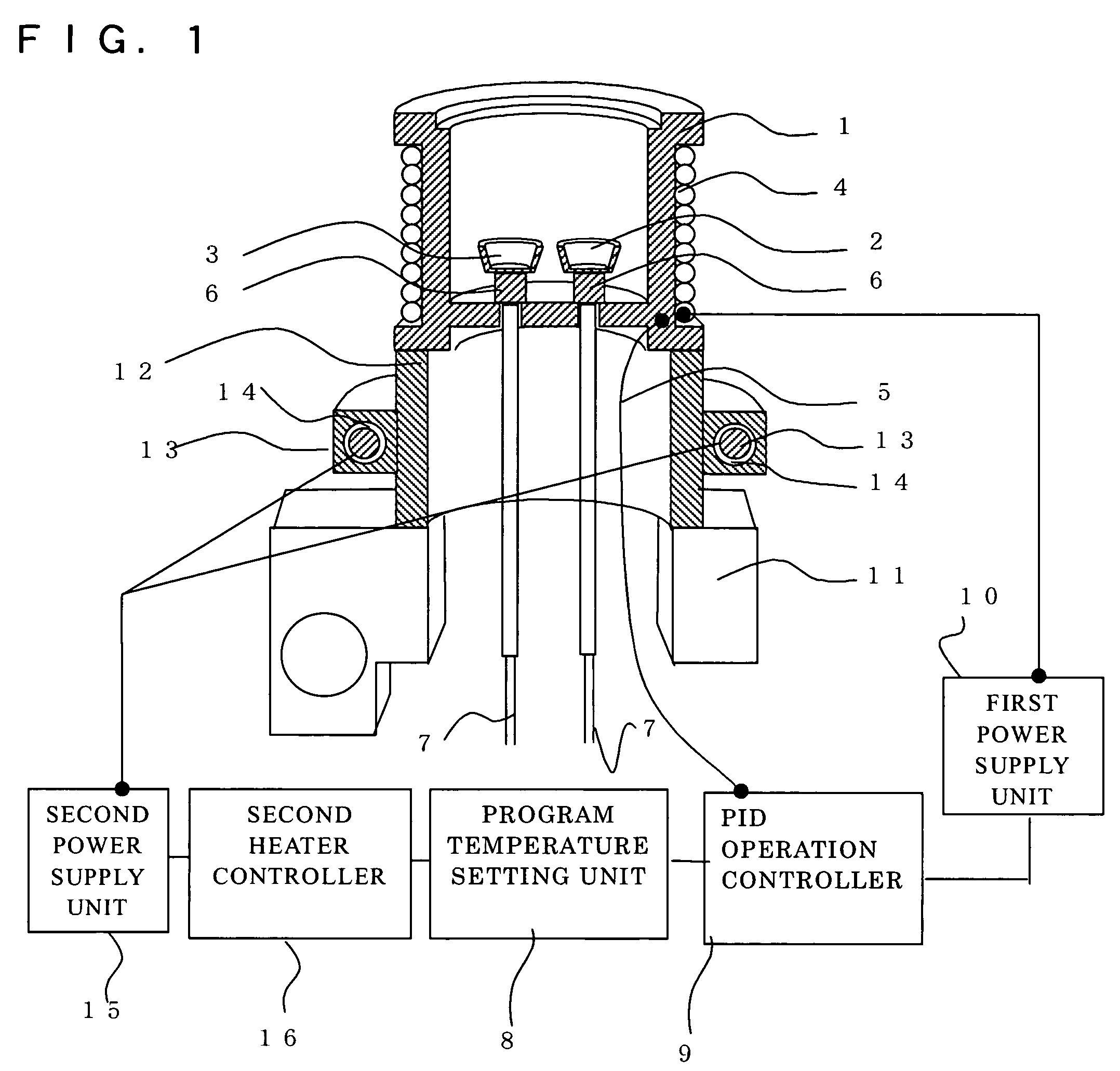
[0010]A description is now given using FIG. 1 of a differential scanning calorimeter equipped with a second heater of the present invention. A sample holder 2 and a reference material holder 3 are provided within a chamber inside the heat sink 1. A first heater 4, with an insulation film, for heating the heat sink 1 and a heat control electrode 5 for detecting heat sink temperature and producing a temperature detection signal for controlling feedback are provided on a side surface of the heat sink 1.

[0011]A differential heat flow detector 6 is provided between a bottom plate of the heat sink 1, and the sample holder 2 and reference material holder 3. Thermocouple elements 7 are then welded to the differential heat flow detector 6 and a temperature difference between the sample and the reference material is detected. The temperature difference signal is outputted as a heat flow difference signal flowing into the sample side and the reference material side.

[0012]An arbitrary temperatu...


PUM

PropertyMeasurementUnit
temperatureaaaaaaaaaa

Abstract

A differential scanning calorimeter has a heat sink for accommodating therein a measurement sample and a reference material, and a differential heat flow detector that detects a temperature difference between the sample and the reference material. A cooling mechanism cools the heat sink, and a thermoconductor is disposed between the cooling mechanism and the heat sink and forms a heat flow path between the two. A first heater heats the heat sink, and a second heater heats the thermoconductor to thereby heat the heat sink. The second heater begins operating before the first heater nears its rated maximum output power.

Description

BACKGROUND OF THE INVENTION[0001]The present invention relates to a differential scanning calorimeter for a thermal analyzer.[0002]A differential scanning calorimeter of a thermal analyzer is equipped with a heat-controlled heat sink, a sample within the heat sink, a reference material holder, a heater for heating the heat sink, and a cooling device for cooling the heat sink. With differential scanning calorimeters of the related art, a cooling device comes into direct contact with a heat sink so as to cool the heat sink. Cooling devices taking liquid nitrogen as a medium are disclosed in Japanese issued Patent Tokkohei 2-116744 and Japanese issued Patent Tokkohei 7-122619. At the cooling device, an electrical cooling device that compresses a cooling agent using a compressor so as to cause adiabatic expansion that in turn produces cooling is provided. A metallic member connected to the electrical cooling device then makes direct contact with a heat sink so as to cause cooling.[0003]...

Claims


Application Information

Patent Timeline
Patent Type & Authority Patents(United States)
IPC IPC(8): G01K17/08G01N25/20G01N25/48
CPCG01N25/4866G01N25/4826
Inventor NISHIMURA, SHINYANAKATANI, RINTAROKINOSHITA, RYOICHI
Owner HITACHI HIGH TECH SCI CORP
Learn More