Surgical handpiece tip

a surgical and handpiece technology, applied in the field of handpieces, can solve the problems of difficult temperature control of heated solutions and deteriorating vision, and achieve the effect of rapid boiling any surgical fluid

Inactive Publication Date: 2007-10-02
NOVARTIS AG
View PDF57 Cites 30 Cited by
  • Summary
  • Abstract
  • Description
  • Claims
  • Application Information

AI Technical Summary

Benefits of technology

[0009]The present invention improves upon the prior art by providing a surgical handpiece having a tip with at least two coaxially spaced electrically conductive tubes. The tubes are separated by an electrical insulator. The interior of the inner tube is used for aspiration of liquefied tissue. The outer tube is surrounded by a soft irrigation sleeve that forms an irrigation fluid path. The distal portion of the interior tube terminates inside of the outer tube so as to form a boiling region. Surgical fluid from the irrigation fluid path can enter the boiling region through a hole or port in the outer tube. Electrical current is passed between the inner and outer tube to rapidly boil any surgical fluid in the boiling region. The boiling fluid rapidly expands out of the ring between the tube ends and forces hot fluid to contact the targeted tissue, thereby liquefying the tissue and allowing the tissue to be aspirated. Such a construction allows the boiling chamber to be self-priming and operate even if the outer tube is occluded with material.

Problems solved by technology

When age or disease causes the lens to become less transparent, vision deteriorates because of the diminished light which can be transmitted to the retina.
Temperature control of the heated solution can be difficult because the fluid tubings feeding the handpiece typically are up to two meters long, and the heated solution can cool considerably as it travels down the length of the tubing.

Method used


Image

  • Surgical handpiece tip
  • Surgical handpiece tip
  • Surgical handpiece tip

Examples


Embodiment Construction

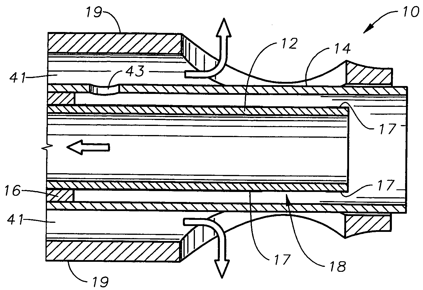
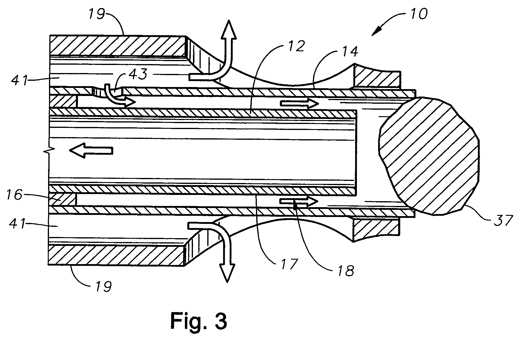
[0018]As best seen in FIGS. 1 and 3, in the present invention tip 10 to be used with handpiece 9 generally includes inner tube 12 and outer tube 14 separated by insulator 16. Inner tube 12 has any suitable inside diameter, such as about 0.028 inches, and any suitable outside diameter, such as about 0.032 inches. Outer tube 14 has any suitable outside diameter, such as about 0.042 inches. Inner tube 12 and outer tube 14 may be made of any electrically conductive material, such as stainless steel or titanium tubing. Insulator 16 may be made of any electrically nonconductive material resistant to high temperatures, such as polyimide, silicone or ceramic. Insulator 16 may be any suitable thickness, for example, about 0.003 inches. Inner tube 12 may also contain dielectric coating 17 having a portion removed so as to form an annular boiling region 18. Coating my be any suitable material, with vapor deposited parylene being preferred.

[0019]Outer tube 14 extends distally past inner tube 12...


PUM


Abstract

A surgical handpiece having a tip with at least two coaxially spaced electrically conductive tubes. The tubes are separated by an electrical insulator. The interior of the inner tube is used for aspiration of liquefied tissue. The outer tube is surrounded by a soft irrigation sleeve that forms an irrigation fluid path. The distal portion of the interior tube terminates inside of the outer tube so as to form a boiling region. Surgical fluid from the irrigation fluid path can enter the boiling region through a hole or port in the outer tube. Electrical current is passed between the inner and outer tube to rapidly boil any surgical fluid in the boiling region. The boiling fluid rapidly expands out of the ring between the tube ends and forces hot fluid to contact the targeted tissue, thereby liquefying the tissue and allowing the tissue to be aspirated. Such a construction allows the boiling chamber to be self-priming and operate even if the outer tube is occluded with material.

Description

BACKGROUND OF THE INVENTION[0001]This invention relates generally to the field of minimally invasive surgery, such as intervertebral disc and cataract surgery and more particularly to a handpiece for practicing the liquefraction technique.[0002]The human eye in its simplest terms functions to provide vision by transmitting light through a clear outer portion called the cornea, and focusing the image by way of the lens onto the retina. The quality of the focused image depends on many factors including the size and shape of the eye, and the transparency of the cornea and lens.[0003]When age or disease causes the lens to become less transparent, vision deteriorates because of the diminished light which can be transmitted to the retina. This deficiency in the lens of the eye is medically known as a cataract. An accepted treatment for this condition is surgical removal of the lens and replacement of the lens function by an artificial intraocular lens (IOL).[0004]In the United States, the...

Claims


Application Information

Patent Timeline
Patent Type & Authority Patents(United States)
IPC IPC(8): A61B18/18A61B18/04A61B17/56A61B17/32A61F9/007
CPCA61F9/00736A61B17/3203A61F9/00745A61B2018/044
Inventor MADDEN, SEAN C.
Owner NOVARTIS AG
Why Eureka
Try Eureka