Process for manufacturing a track and stripping device

a manufacturing process and technology for stripping devices, applied in the field of manufacturing a track and stripping device, can solve the problem of requiring a complex drum production

Inactive Publication Date: 2007-10-02
MICHELIN RECH & TECH SA
View PDF7 Cites 0 Cited by
  • Summary
  • Abstract
  • Description
  • Claims
  • Application Information

AI Technical Summary

Benefits of technology

[0028]The fact that the joint surface of the two die-halves constituting the inner mold is positioned outside the midplane of the cavities formed on the inner mold (in the assembly configuration for the manufacture of a track) makes it possible to systematically maintain the track on the second die-half during the stripping operation, and thus to facilitate the arrangement of the manufacturing workshop in consequence.
[0030]Advantageously, the filling of the cavities may be performed by extrusion or injection molding of a blend inside the cavities for molding the drive blocks before laying the armatures and other blends constituting the track belt. The filling by extrusion or injection molding makes it possible to avoid operations, that are always difficult, of manipulation and brightening of the contact surfaces between different blends to maintain a satisfactory crude bonding between the block blend and the armature blend placed radially on top.
[0032]Moreover, and so as to limit unwanted flows of rubber that can form molding defects, such as flash, during the molding operation, while at the same time reducing the sensitivity to the volume dispersions between the raw track blanks to be molded and vulcanized successively in the same mold, it is prudent to arrange for the components of the sectors of the outer mold to be individually mobile, along a direction of approach to or of distancing from the axis of the mold at least on a final molding course, such components also being circumferentially mobile with respect to each other at least while they are moving along the course. The latter arrangement makes it possible to preserve the integrity of the outer mold by avoiding any premature deterioration during the molding operation.
[0035]The advantage afforded by this type of mold combined with the manufacture of a raw track blank on a rigid inner mold lies in the fact that a certain amount of elasticity is imparted to the outer mold; that is to say, a certain capacity is provided to increase the volume of the molding cavity slightly so as to follow the expansion of the elastomeric materials resulting from the increase in temperature and, for example, at and above a predetermined molding pressure threshold, while at the same time perfectly distributing the play between the components of the outer mold.
[0037]The combination of the preceding arrangements makes it possible to achieve high-quality molding while at the same time avoiding the deterioration of the outer or inner molds that might result from an uncontrolled pressure increase due to the expansion of the blends during the molding operation.
[0043]the gripping means making it possible, once the inner mold with the vulcanized track is in place on the device and the first blocking means are blocking the axial movement of the first die-half of the mold, to move the second die-half axially so as to separate it from the first die-half and to release the second die-half from the track, the track being blocked axially by the second blocking means.

Problems solved by technology

This process has the drawback of requiring a complex production of a drum, the components of which must be retractable after molding and vulcanization of the band so as to allow the band to be stripped out after molding.
This process has a certain number of drawbacks, including:it is imperative to determine with very high precision the volumes of the blends and of the armatures, since the molding volume delimited by the outer mold and the base cylindrical drum (acting as the inner mold) very precisely regulates the volume of the track to be molded, and since the elastomer blends used are, by their nature, incompressible;the overhang of the various outer mold components requires high-precision mechanics to avoid having areas of overthickness or areas of imperfect molding when the hollows of the outer mold are not filled before being applied against the belt; andduring the stripping of the track from the inner mold by axial separation of the two die-halves constituting the mold, the track randomly follows one or other of the die-halves, which is not convenient in an industrial environment in which such a large, heavy track needs to be manipulated, without knowing, in principle, which side of the drum to take it from in order to move it.

Method used


Image

  • Process for manufacturing a track and stripping device
  • Process for manufacturing a track and stripping device
  • Process for manufacturing a track and stripping device

Examples


Embodiment Construction

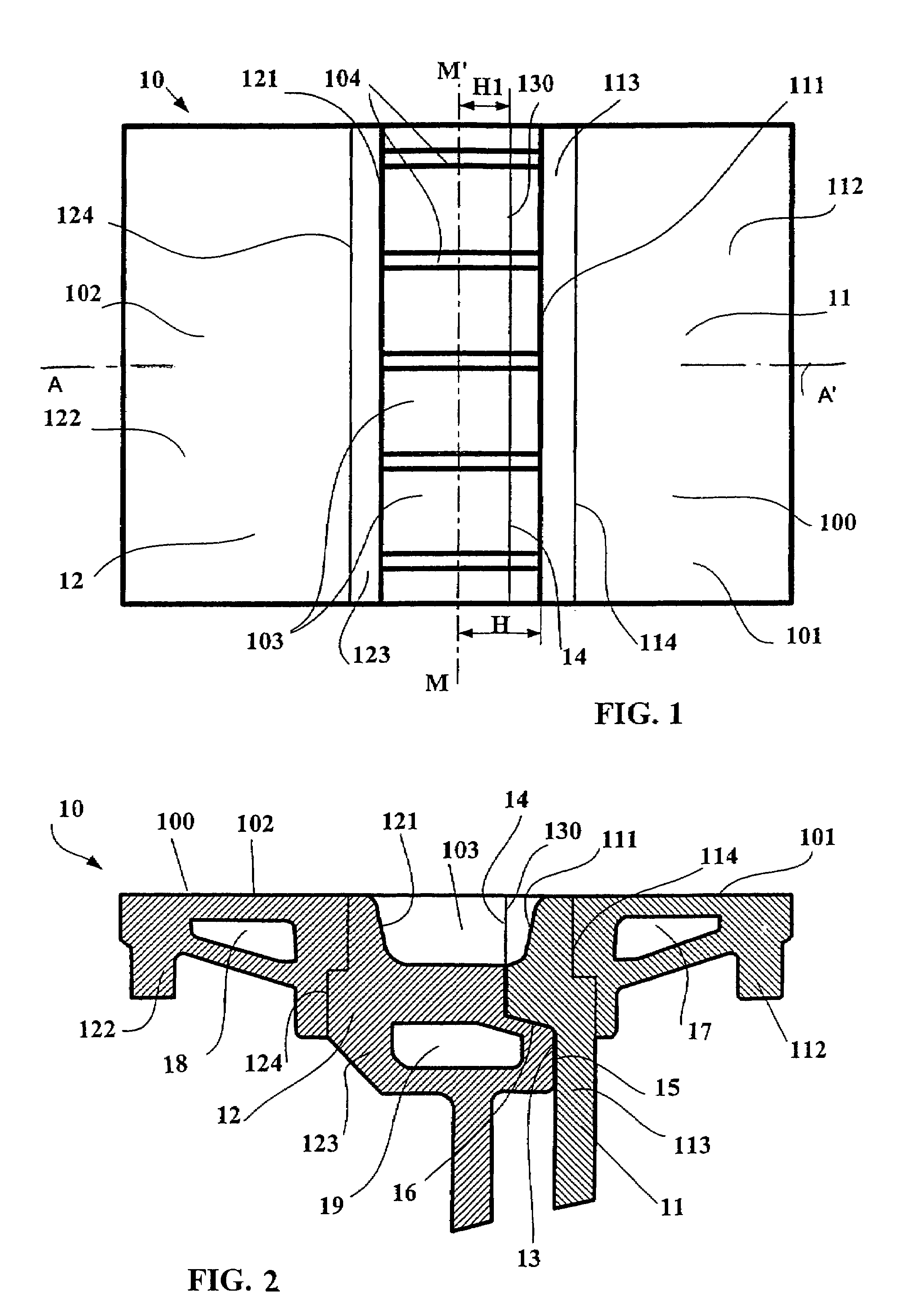
[0055]FIGS. 1 and 2 show partial views of the same inner mold 10 intended to be used to manufacture a track blank. In FIG. 2, showing a radial cross section of the mold 10 (that is to say, containing the axis of the inner mold), there can be seen a first cylindrical die-half 11, whose axis merges with the axis of the inner mold, and a second cylindrical die-half 12, whose axis also merges with the axis of the inner mold, the die-halves being represented in the assembly position before the start of manufacture of a new track. Once assembled, the die-halves 11, 12 are in contact along a joint surface 13 (FIG. 2) formed in the present case from two flat surfaces 14, 15 perpendicular to the axis of the inner mold 10 and from a frustoconical surface 16 of the same axis, the frustoconical surface 16 linking the flat surfaces 14, 15. Clamping means (diagrammatically represented in FIG. 11) keep the die-halves 11, 12 securely attached throughout the stage of manufacturing and molding the tr...


PUM

PropertyMeasurementUnit
circumferenceaaaaaaaaaa
distanceaaaaaaaaaa
mechanical behavioraaaaaaaaaa

Abstract

A process for manufacturing a track formed from a circumferentially continuous belt made of elastomeric material and including an inner surface and an outer surface. The inner surface is provided with a plurality of drive blocks uniformly arranged on the circumference. The process includes a step in which a cylindrical inner mold formed by first and second cylindrical die-halves is assembled, the two die-halves being movable relative to each other in an axial direction to come into contact with each other at a joint surface. The inner mold includes a radially external laying surface provided with a plurality of uniformly spaced cavities for molding the drive blocks, each cavity being delimited in the axial direction by respective side walls of the first and second die halves. The joint surface of the two die-halves is axially closer to one side wall than to the other side wall. A device for stripping the track from the inner and outer molds is provided.

Description

CROSS REFERENCE TO RELATED APPLICATIONS[0001]This is a continuation of international application PCT / EP01 / 08428 filed Jul. 20, 2001, which was published in French on Jan. 31, 2002 as international publication WO 02 / 07956 A1 which claims priority of French application 00 / 09701 filed Jul. 24, 2000.BACKGROUND OF THE INVENTION[0002]1. The Field of Invention[0003]The invention relates to a process for manufacturing and molding tracks made of elastomeric material. The invention also relates to a device for stripping out such tracks.[0004]2. The Related Art[0005]The use of tracks is developing in many sectors, especially that of agricultural tractors or other civil engineering machines for which the conditions of mixed rolling (both on loose ground and on roads) entail increasing quality requirements for the tracks and also reduced industrial costs.[0006]In the text hereinbelow, the term “elastomeric material” denotes a material comprising at least one elastomer that can be reinforced with...

Claims


Application Information

Patent Timeline
Patent Type & Authority Patents(United States)
IPC IPC(8): B29C45/14B29C47/02B29C43/50B62D55/253B29D29/00B29D29/08B29K21/00B62D55/32
CPCB29C43/50B29D29/085B29L2031/7094B29D29/08
Inventor MENARD, GILBERTGAUTHIER, GILBERT
Owner MICHELIN RECH & TECH SA
Why Eureka
Try Eureka