Microchannel heat sink

a heat sink and microchannel technology, applied in the direction of electrical equipment construction details, lighting and heating apparatus, laminated elements, etc., can solve the problems of thermal performance degradation of conventional microchannel heat sinks along their length, and achieve the overall heat removal rate of the heat sink, enhance the heat removal rate of the microchannel heat sink, and enhance the heat removal ra

Active Publication Date: 2007-10-02
PURDUE RES FOUND INC
View PDF13 Cites 36 Cited by
  • Summary
  • Abstract
  • Description
  • Claims
  • Application Information

AI Technical Summary

Benefits of technology

[0007]The present invention provides in one embodiment a microchannel heat sink as well as method that includes one or more microchannels for receiving a working fluid flows to remove heat and one or more recesses disposed in a surface communicated to the one or more of the microchannels to enhance heat removal rate of the microchannel heat sink.
[0008]In an illustrative embodiment of the invention, the one or more recesses can be located at one or more local hot spot regions of a heat-generating component to enhance heat transfer rates at the local regions as well as the overall heat removal rates of the heat sink.
[0009]In another illustrative embodiment of the invention, the heat sink includes a cover that closes off the one or more microchannels. The cover has the one or more recesses in a cover surface facing the microchannels such that the recesses communicate to the microchannels and thus the working fluid to enhance heat transfer rate of the microchannel heat sink.
[0012]The invention is advantageous to provide enhancement of localized heat transfer rates to lower maximum chip temperatures in microelectronic apparatus as well as to achieve lower temperature gradients on chips to reduce thermal stresses, improve reliability and increase chip performance. These advantages are achieved using the one or more recesses to provide passive flow modulation with a smaller pressure drop across the microchannels and hence with a lower pumping power.

Problems solved by technology

However, conventional microchannel heat sinks experience deterioration in thermal performance along their length as the boundary layers continue to develop and thicken with downstream fluid travel.

Method used


Image

  • Microchannel heat sink
  • Microchannel heat sink
  • Microchannel heat sink

Examples


Embodiment Construction

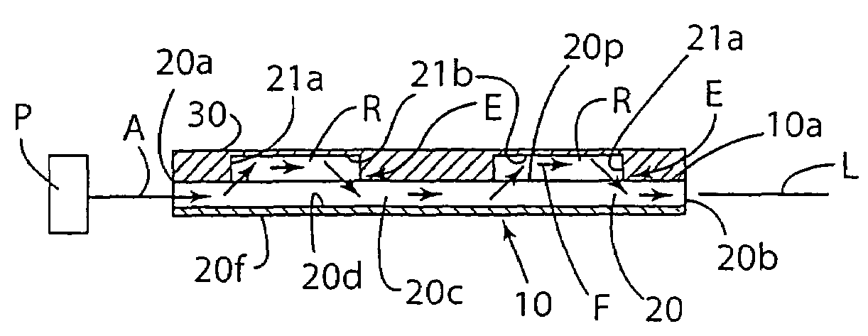
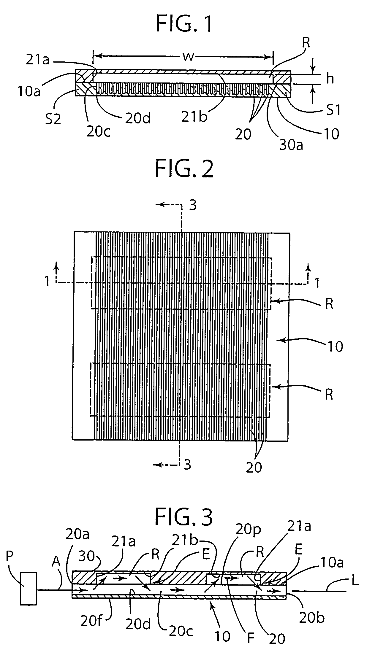
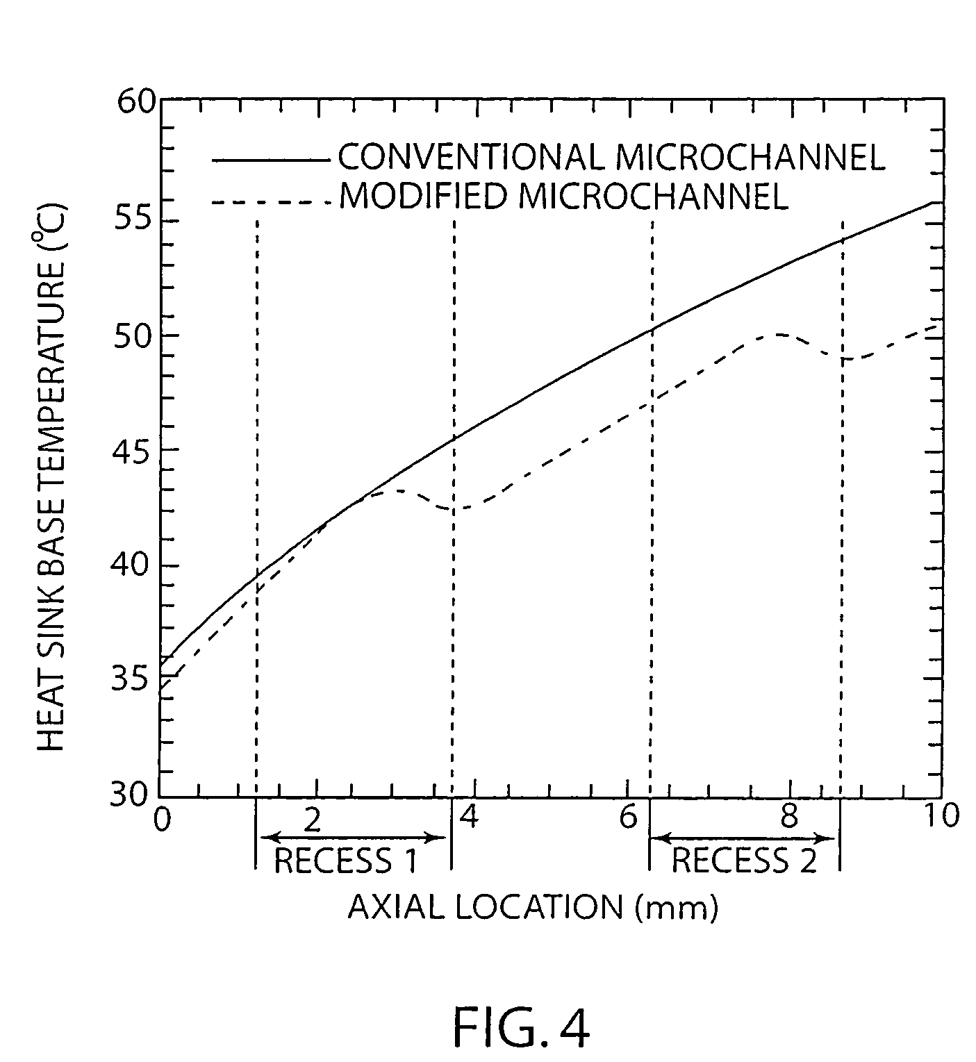
[0019]The present invention provides an improved microchannel heat sink as well as method embodying the heat sink, having enhanced localized and global (overall) heat transfer rates, and useful for, although not limited to, removing heat from a heat-generating electronic component, such as for purposes of illustration and not limitation, a microelectronic IC chip (integrated circuit chip) of an electronic device such as cell phones, laptop computers, personal digital assistance devices, desktop computers, and the like. A microchannel heat sink as well as method pursuant to an embodiment of the invention that includes one or more microchannels through which a working fluid flows to remove heat from a heat-generating component, such as a microelectronic chip, and one or more recesses disposed in a surface communicated to the one or more of the microchannels to enhance local and overall heat removal rate of the microchannel heat sink. For purposes of illustration and not limitation, an...


PUM


Abstract

A microchannel heat sink as well as method includes one or more microchannels through which a working fluid flows to remove heat from a heat-generating component, such as a microelectronic chip, and one or more recesses disposed in a surface communicated to the one or more of the microchannel to enhance heat transfer rate of the microchannel heat sink. The recesses can be located in a surface of a cover that closes off the microchannels. The one or more recesses can be located at one or more local hot spot regions to enhance heat transfer rates at the local regions as well as overall heat removal rate of the heat sink.

Description

[0001]This application is a continuation of International Application No. PCT / US2004 / 042801 filed on Dec. 8, 2004, which claims benefits and priority of provisional application Ser. No. 60 / 557,784 filed on Mar. 30, 2004.CONTRACTUAL ORIGIN OF THE INVENTION[0002]The invention was made in part with United States Government support under grant / contract Number 670-1288-6398 awarded by the National Science Foundation (NSF I / UCRC). The Government may have certain rights in the invention.FIELD OF THE INVENTION[0003]The invention relates to a microchannel heat sink having improved rates of heat transfer.BACKGROUND OF THE INVENTION[0004]Rapidly decreasing features sizes and increasing power density in microelectronic devices has necessitated development of novel cooling strategies to achieve very high heat removal rates from these devices. For example, heat removal rates in excess of 200 W / cm2 have been projected for the next generation of personal computing devices. Microchannel heat sinks h...

Claims


Application Information

Patent Timeline
Patent Type & Authority Patents(United States)
IPC IPC(8): H05K7/20H01L23/473H02H1/00
CPCH01L23/3677H01L23/473F28F3/12F28F2260/02H01L2924/0002H01L2924/09701H01L2924/00
Inventor LEE, POH-SENGGARIMELLA, SURESH V.
Owner PURDUE RES FOUND INC
Why Eureka
Try Eureka