Biomedical recognizing system comprising image diagnosis workstation and method therefor

a biomedical and image recognition technology, applied in the field of diagnostic image information, can solve problems such as ineffective use of the specified method of an operator or an individual, ineffective password entry and inability to effectively enter the password each time for keeping security

Inactive Publication Date: 2007-10-02
EIZO NANAO
View PDF10 Cites 7 Cited by
  • Summary
  • Abstract
  • Description
  • Claims
  • Application Information

AI Technical Summary

Benefits of technology

[0013]The diagnostic image is linked to a manufacturing information of the displa

Problems solved by technology

In the present circumstances, there has been used no effective method of specifying an operator or an individual.
When the medical doctor becomes apart from the diagnostic image, then a security problem may be caused.
The entry of a password each time for keeping the security is not efficient.
As shown in FIG. 3(a), the present system has utilized a method of making the medical doctor, who intends to

Method used


Image

  • Biomedical recognizing system comprising image diagnosis workstation and method therefor
  • Biomedical recognizing system comprising image diagnosis workstation and method therefor
  • Biomedical recognizing system comprising image diagnosis workstation and method therefor

Examples


Embodiment Construction

[0025]The present invention will be described in details with reference to the accompanying drawings.

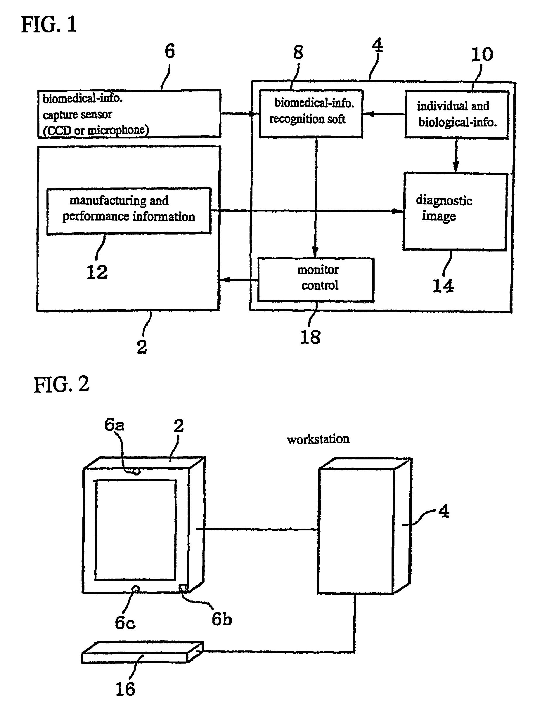
[0026]FIG. 1 is a block diagram illustrative of an embodiment of a biomedical recognition system with a CRT image diagnostic workstation in accordance with the present invention. A biomedical recognition system comprises a CRT monitor 2, a workstation 4 connected to the CRT monitor 2, and a sensor connected to the workstation 4 for capturing biomedical informations.

[0027]The CRT monitor 2 is a monitor of the workstation 4 for displaying a medical image 14. An image display device is not limited to the CRT. Any computer displays for displaying an image are available such as liquid crystal displays, plasma displays, and EL-displays.

[0028]The CRT monitor 2 stores and sends, to the workstation 4, manufacturing information including manufacturing dates, manufacturing numbers, manufacturing places, and performance information 12 including variations over times such as brightness, gamma-cha...


PUM


Abstract

A biomedical recognition system includes diagnostic image information obtained by taking an image of a patient, a workstation storing the diagnostic image information, and a display device for displaying the diagnostic image information. A sensor is provided for capturing a biomedical information of a doctor. A biomedical information recognition system is connected to the sensor and integrated in the workstation for comparing a previously registered biomedical information and the biomedical information captured by the sensor. A display device control system is provided for causing the display device to display a diagnostic image linked to the biomedical information if a comparing result indicates a correspondence between the previously registered biomedical information and the biomedical information captured by the sensor, and for causing the display device to discontinue a part of functions thereof if the comparing result indicates a non-correspondence between the information.

Description

TECHNICAL FIELD[0001]The present invention relates to a diagnostic image information obtained through a radiography of patient, and a workstation storing the diagnostic image information as well as a display for displaying the diagnostic image information.BACKGROUND OF THE ART[0002]In the past few years, a CRT image diagnosis using a CRT monitor has been becoming active in the United States of America and the European countries. In 2000, a percentage of spread thereof in the world market is approximately 5 percent to 8 percent. In eight years from now, about 70 percent of the spread may be estimated. The CRT image diagnosis uses any displays utilizing an electrical display system instead of the conventional diagnostic X-ray film. A diagnostic display monitor as electrical display is in contrast to the X-ray film in view of the following. For an input device, a data storage device and a CRT image diagnosis device, there is needed information about when those devices were manufactured...

Claims


Application Information

Patent Timeline
IPC IPC(8): H04K1/00G06T7/00G16H30/40H04N7/18
CPCG06F19/321H04N7/18G06T7/0012G06T2207/30004G16H30/40
Inventor TODAKA, CHIAKIOHASHI, MITSUOSIMPSON, RONFURUKAWA, TOSHIHIKO
Owner EIZO NANAO
Why Eureka
Try Eureka