Engine block die-casting apparatus having mechanically actuated bank core slides

a technology of die-casting apparatus and core slide, which is applied in the direction of metal-working apparatus, mold handling equipment, manufacturing tools, etc., can solve the problems of high operational and maintenance costs, substantial waste of die-cast parts, and cost-effective solutions, and achieves enhanced dimensional stability of the bank core slide assembly, high repeatability, and high repeatability

Inactive Publication Date: 2007-10-09
AAR KEL ENTERPRISES
View PDF8 Cites 21 Cited by
  • Summary
  • Abstract
  • Description
  • Claims
  • Application Information

AI Technical Summary

Benefits of technology

[0015]In this manner, the present invention overcomes the inefficiencies and high operational and maintenance costs of conventional die-casting machines employed to produce engine blocks. The present invention eliminates the requirement for large complex hydraulic cylinders and their associated hardware to insert and extract the bank core slide assemblies into and out of the die cavity. By employing mechanically, rather than hydraulically actuated bank core slides, the present invention ensures an accurate, highly repeatable, and dimensional stable placement of the bank core slide assemblies in the die cavity. Additionally, by eliminating the complex arrangement of hydraulic cylinders and actuators that are normally mounted outside the ejector holder block in conventional die-casting machines, the present invention allows a full lock of the die elements against the rear of the bank core slides. This locking feature provides further enhanced dimensional stability of the bank core slide assemblies over that of the conventional die-casting machines.

Problems solved by technology

When driven to the closed position, the alignment and the placement of the cylinder cores within the die cavity are critical as misalignment can vary wall thicknesses and distort surface dimensions to unacceptable limits and result in a substantial waste of die-cast parts.
When die-casting an engine block, properly locking the bank core slide assemblies and accurately retaining them in the desired position to maintain the dimensional stability of the bank core slides, and thus the cast cylinder bores is somewhat problematic.
However, this is not a cost effective solution and not only increases the costs of materials but also increases the time and labor costs in producing a usable engine block.
Additionally, forming of the cylinder walls in a die-cast engine block places a great deal of formed metal about the core inserts of the bank core slides.
However, the solidified cast metal tends to hold the core inserts and the bank core slide assemblies in place and makes extraction of the core inserts from the formed cylinder bores difficult.
These large hydraulic actuating assemblies require high hydraulic pressures to overcome the hold of the cast metal on each of the core inserts.
Furthermore, due to the length of the stroke necessary to extract the cores inserts from the cast engine block and their sheer physical size, the hydraulic actuating assemblies must be located outside of the ejector holder block and back from the bank core slides.
This necessitates further complexity in connecting the bank core slide assemblies to the externally mounted hydraulic actuating assemblies.
In addition to these issues, as in all die-casting processes, some small quantities of the extra molten casting material escapes from, or is forced into the areas where the die elements join.
As this extra material solidifies, it forms waste casting debris.
Any flashing that remains attached to, or between, the die elements and core inserts of the die-casting dies will interfere with the next die-casting process and may damage subsequent castings if it is not removed after each casting extraction.
Conventional die-casting dies are generally not capable of self-cleaning or clearing the flashing so that human intervention is required to ensure that the die elements and cores are clear of flashing and debris after each casting event.
This is a time consuming and difficult procedure to perform in the tight, highly heated confines of an engine block die-casting machine.
Furthermore, conventional die-casting dies fail to address the dissipation of the heat inherent in the die-casting process.
This disregard of the heat from the casting process negatively affects the maintenance and repair costs.
This affects the dimensional stability of the core inserts.
This uneven dissipation introduces temperature differences and subsequent dimensional differences or instabilities between the core inserts of the two bank core slide assemblies and between the individual core inserts of each bank, which may cause unacceptable dimensional variations.
In addition, the core slides become heat stressed such that their metallurgical properties change causing them to wear rapidly in their interaction with the formed castings.
This rapid wearing of the core inserts requires that they be replaced often, which greatly adds to the maintenance costs and down time of the die-casting dies.

Method used


Image

  • Engine block die-casting apparatus having mechanically actuated bank core slides
  • Engine block die-casting apparatus having mechanically actuated bank core slides
  • Engine block die-casting apparatus having mechanically actuated bank core slides

Examples


Embodiment Construction

)

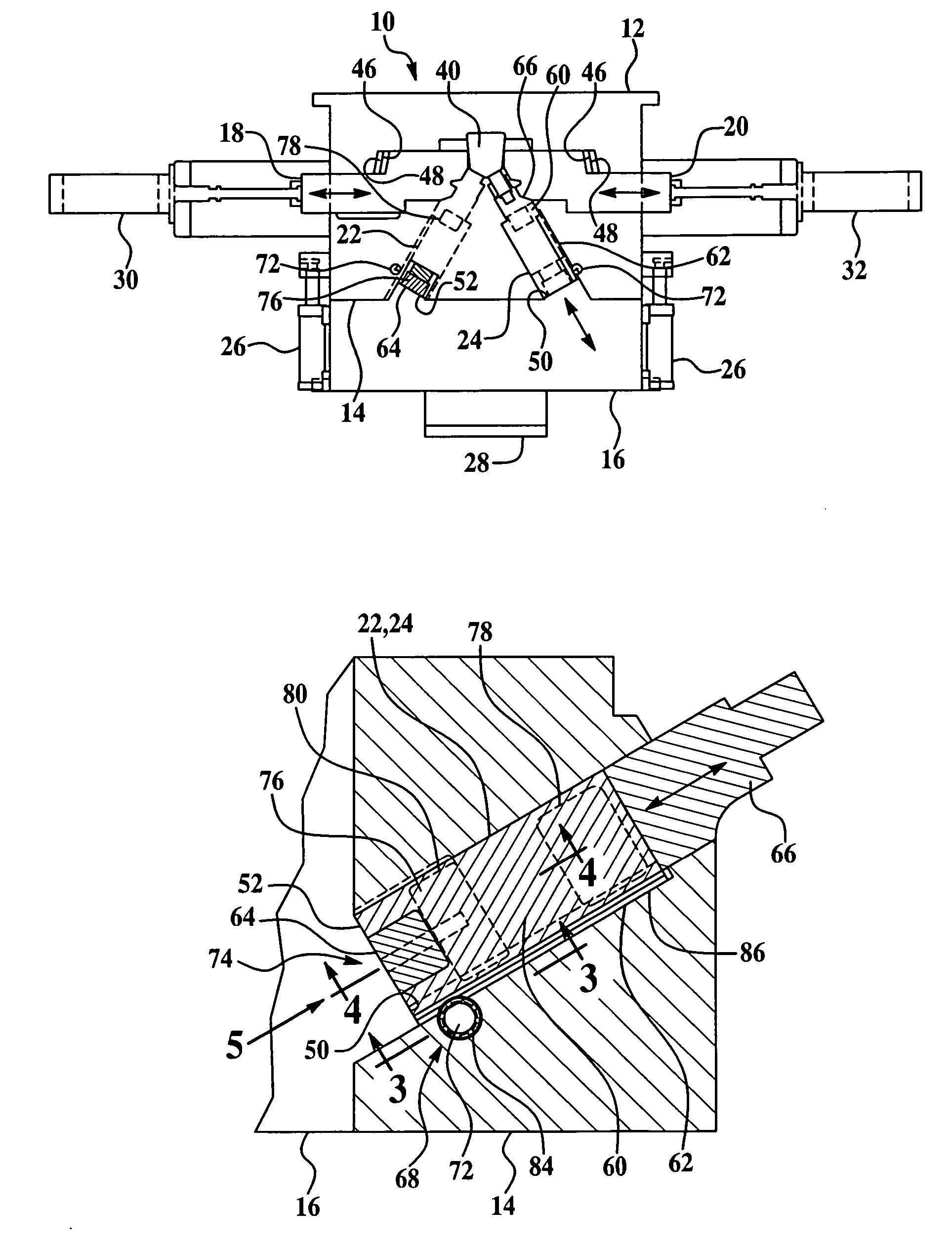
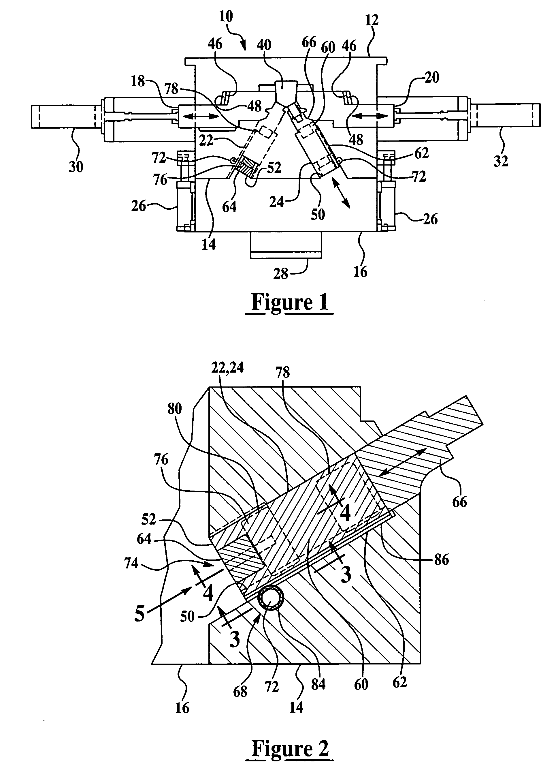
[0022]The engine block die-casting apparatus of the present invention is generally indicated at 10 in FIG. 1. It should be appreciated by those having ordinary skill in the art that the engine block die-casting apparatus 10 of the present invention may be configured to produce a variety of engine block types having any number of cylinders. However, as an illustrative example, the engine block die-casting apparatus 10 described herein is configured to produce “V” type engine blocks. Referring to FIG. 1, the engine block die-casting apparatus 10 includes a stationary element 12, an ejector holder block 14 adapted to be operatively movable to and from said stationary element 12, an ejector box 16, a pair of side core slides 18 and 20, and at least one bank core slide assembly slidably mounted to and operatively moveable within the ejector holder block 14 that is adapted to be mechanically actuated. In the preferred embodiment illustrated in FIG. 1 where the apparatus 10 is configured ...


PUM

PropertyMeasurementUnit
adhesionaaaaaaaaaa
temperatureaaaaaaaaaa
pressuresaaaaaaaaaa

Abstract

An engine block die-casting apparatus of the present invention includes a stationary element, an ejector holder block adapted to be operatively movable to and from the stationary element, and an ejector box. The apparatus also includes a pair of side slide cores and at least one bank core slide assembly that is slidably mounted and mechanically actuated within the ejector holder block. The stationary element, the ejector holder block, the pair of side slide cores, and the bank core slide assembly are adapted to be moved proximate each other so as to create a closed die-cast cavity and to be drawn apart from one another to allow extraction of the cast engine block.

Description

CROSS REFERENCE TO RELATED APPLICATIONS[0001]This application claims the benefit of U.S. provisional patent application entitled “Engine Block Die-Casting Apparatus Having Mechanically Actuated Bank Core Slides,” having Ser. No. 60 / 652,360, and filed on Feb. 11, 2005.BACKGROUND OF THE INVENTION[0002]1. Field of the Invention[0003]The present invention relates, generally, to a die-casting apparatus and, more specifically, to a die-casting apparatus having mechanically actuated bank core slide assemblies to produce die-cast engine blocks.[0004]2. Description of the Related Art[0005]Die-casting is widely used in the manufacture of component parts in the automotive industry. Die-casting can provide component parts having complex shapes and surfaces with a high degree of accuracy, which reduces the need for additional machining steps. Furthermore, the accuracy of die-casting provides highly repeatable production processes that can be automated to provide labor cost savings and speed. One...

Claims


Application Information

Patent Timeline
Patent Type & Authority Patents(United States)
IPC IPC(8): B22D17/26B22D33/04
CPCB22D17/22
Inventor PURDY, JIMVAN DAMME, KEVINGAYLARD, DAVID
Owner AAR KEL ENTERPRISES
Why Eureka
Try Eureka