Acoustic noise filter

a filter and acoustic energy technology, applied in the field of acoustic noise filters, can solve the problems of reducing optimal performance, affecting the performance of the filter, and not being able to use specific acoustic frequencies, so as to facilitate cleaning, reduce the collection of particles or silt, and high performance in the filtering of acoustic energy.

Inactive Publication Date: 2007-10-09
NAVY DEPT OF THE
View PDF21 Cites 17 Cited by
  • Summary
  • Abstract
  • Description
  • Claims
  • Application Information

AI Technical Summary

Benefits of technology

[0007]In accordance with the present invention, a liquid flow chamber is enclosed within a radially inner cylindrical support drum on which a cylindrical rubber layer is positioned for exposure through slanted holes of different size in the support drum to the liquid in the flow chamber. A plurality of volumetrically small annular gas cavities of different axial lengths are formed over the rubber layer enclosed within an outer casing for exposure of the rubber layer to gas in opposition to its exposure to the liquid in the flow chamber through a plurality of slanted holes of different size in dimensionally different axial sections of a second cylindrical drum rad

Problems solved by technology

Such filters are however not tunable for use with respect to specific acoustic frequencies.
The rubber cylinder component of such a filter breaks up under acoustic frequencies higher than its breathing mode frequency to thereby reduce optimal perform

Method used


Image

  • Acoustic noise filter
  • Acoustic noise filter
  • Acoustic noise filter

Examples


Embodiment Construction

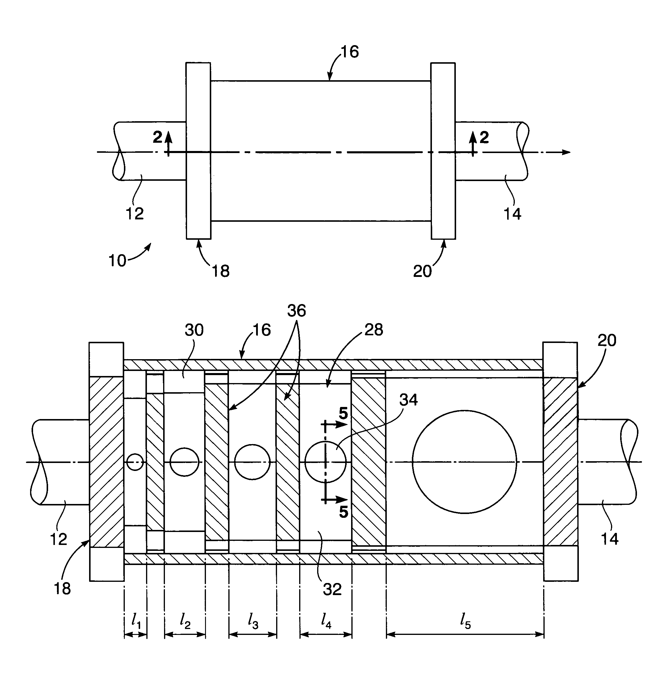
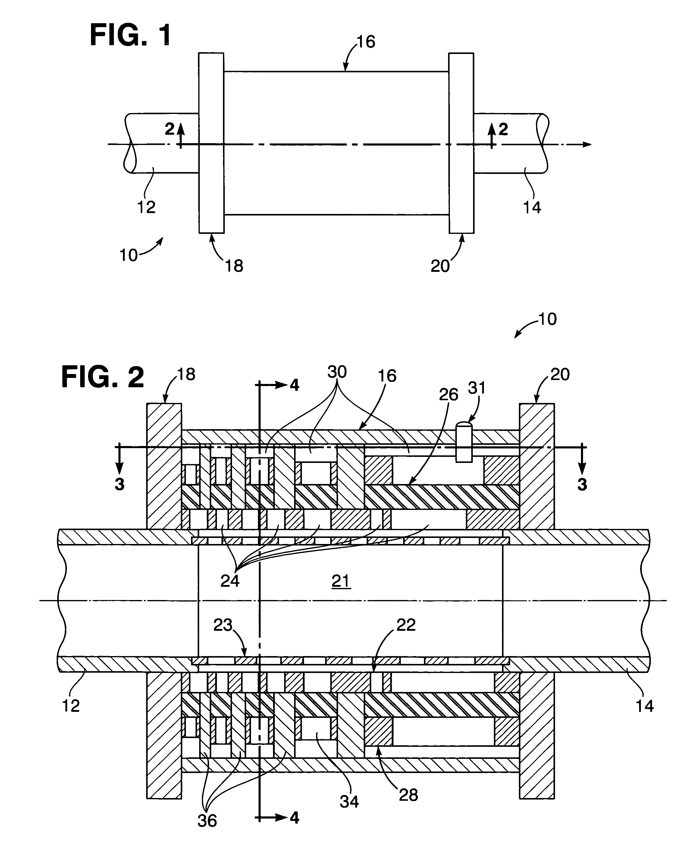
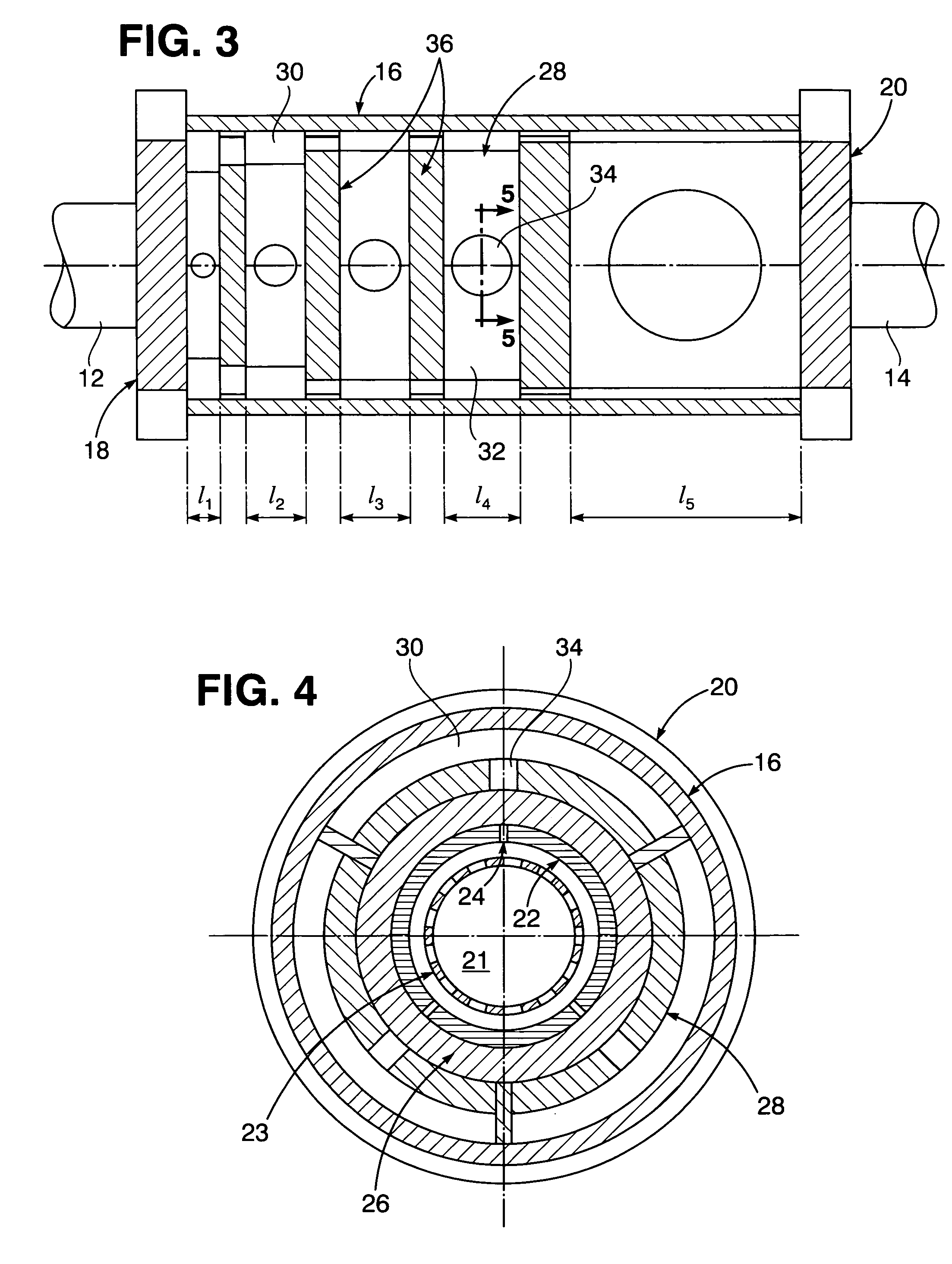
[0013]Referring now to the drawing in detail, FIG. 1 illustrates a reactive acoustic noise filter 10 constructed in accordance with one embodiment of the present invention, having inflow and outflow pipe sections 12 and 14 of a piping system extending from opposite axial ends of the filter 10. The piping system conducts fluid such as liquid which transmits acoustical energy as a source of noise transmitted within the liquid through the filter 10 so as to be reflected and thereby block emission of the noise pursuant to the present invention as hereinafter explained.

[0014]The filter 10 as shown in FIGS. 1 and 2 has an outer cylindrical casing 16 connected to and extending axially between a pair of flanges 18 and 20 from which the pipe sections 12 and 14 respectively extend in axial alignment with each other. Enclosed and confined within the casing 16 is an inner flow chamber 21 through which the liquid is conducted between the pipe sections 12 and 14. Such flow chamber 21 is shown enc...


PUM


Abstract

An acoustic filter is provided with a single flow chamber for exposure of a flexible rubber layer to liquid undergoing flow through the flow chamber with noise producing acoustic energy therein. The flexible rubber layer is supported on a cylindrical drum with slanted holes therein through which the exposure to the liquid in the flow chamber is effected. An axially sectioned drum with dimensionally different diameters, radial thicknesses and slanted holes therein is positioned over the rubber layer within an outer casing to establish a plurality of gas-filled cavities of different axial lengths and separated from each other along the axial length of the liquid flow chamber which is connected at its opposite axial ends by pipe sections to a piping system from which the liquid within the flow chamber is derived.

Description

[0001]The present invention relates to filtering out acoustic noise transmitted within fluid conducted through a piping system.STATEMENT OF GOVERNMENT INTEREST[0002]The invention described herein may be manufactured and used by or for the Government of the United States of America for governmental purposes without the payment of any royalties thereon or therefore.BACKGROUND OF THE INVENTION[0003]Acoustic filters are presently utilized in a variety of fluid filled systems, including those aboard U.S. Navy ships, to block, limit or reduce transmission of noise producing acoustic energy within a range of acoustic frequencies. Such filters are however not tunable for use with respect to specific acoustic frequencies. Currently absorptive types of filters are utilized to absorb acoustic energy, while reactive types of filters are utilized to reflect acoustic energy within a certain frequency range back toward its source in order to quiet the piping system downstream of the filter.[0004]A...

Claims


Application Information

Patent Timeline
IPC IPC(8): F01N1/22F01N1/24F16L55/027F16L55/04
CPCF16L55/054F16L55/02781
Inventor QUIGLEY, JAMES M.
Owner NAVY DEPT OF THE
Why Eureka
Try Eureka