Dynamic magnetic resonance imaging (MRI) with adaptive image quality

a dynamic magnetic resonance imaging and image quality technology, applied in the field of magnetic resonance imaging (mri), can solve problems such as the type of system unsuitable for intravascular mr guided procedures, and achieve the effect of minimising the collection of redundant data

Inactive Publication Date: 2010-09-30
KONINKLIJKE PHILIPS ELECTRONICS NV
View PDF11 Cites 1 Cited by
  • Summary
  • Abstract
  • Description
  • Claims
  • Application Information

AI Technical Summary

Benefits of technology

[0021]Preferably, said tracking element comprises one or more coils located in or on said probe, and said tracking signals comprise spatially encoded signals received thereby. In one exemplary embodiment, the imaging coil is preferably located between two tracking elements in or on said probe, and the three coils are preferably connected to separate receive channels. The imaging coil may, for example, comprise an opposed solenoid imaging coil and the tracking coils may, for example, comprise respective loop coils. In a preferred embodiment, the spatially encoded signals are collected from said tracking coil and said imaging coil in respective successive sets of at least three from at least three respective projections within said image volume. The projections are preferably orthogonal relative to each other. At least three orthogonal projections are required in order to fully characterize the three-dimensional position of the tracking coils. Beneficially, the orthogonal projections from which a set of signals are collected are rotated relative to the orthogonal projections from which the previous set of signals was collected. Thus, each set of collected signals contributes new data to the image and the collection of redundant data is minimised.

Problems solved by technology

This can be cumbersome and makes this type of system unsuitable for intravascular MR guided procedures.

Method used


Image

  • Dynamic magnetic resonance imaging (MRI) with adaptive image quality
  • Dynamic magnetic resonance imaging (MRI) with adaptive image quality
  • Dynamic magnetic resonance imaging (MRI) with adaptive image quality

Examples


Embodiment Construction

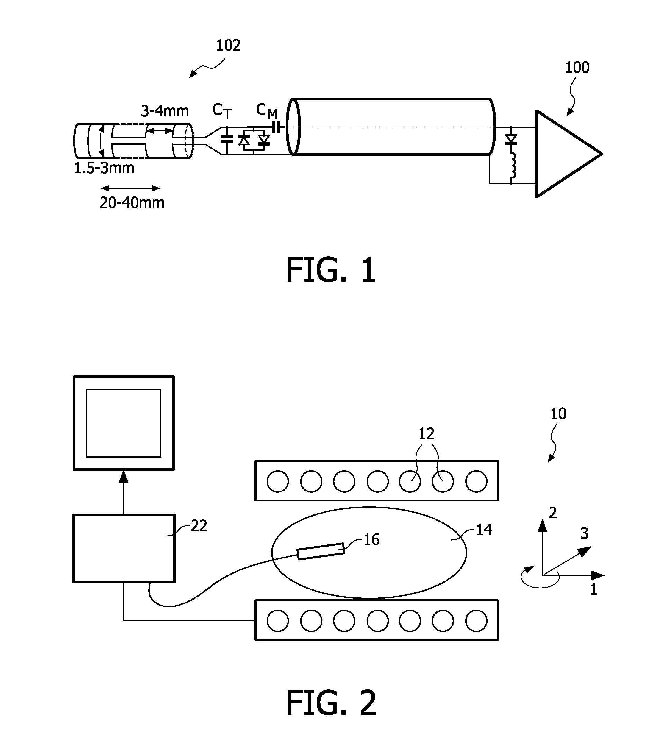
[0030]Referring to FIG. 1 of the drawings, a typical MRI system comprises an MRI scanner 10 having a plurality of radio-frequency transmit coils 12. A subject 14 undergoing an intravascular examination procedure is positioned within the scanner 10 as shown and the coils 12 generate a very strong static magnetic field. As explained above, this magnetic field excites the nuclear spins and realigns their magnetic moments away from the equilibrium position. A circuit (not shown) is provided for modifying the magnetic field by three super-imposed gradients, as described above.

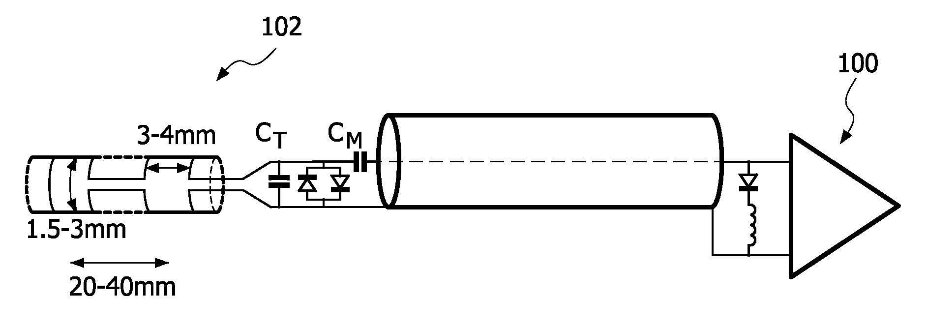
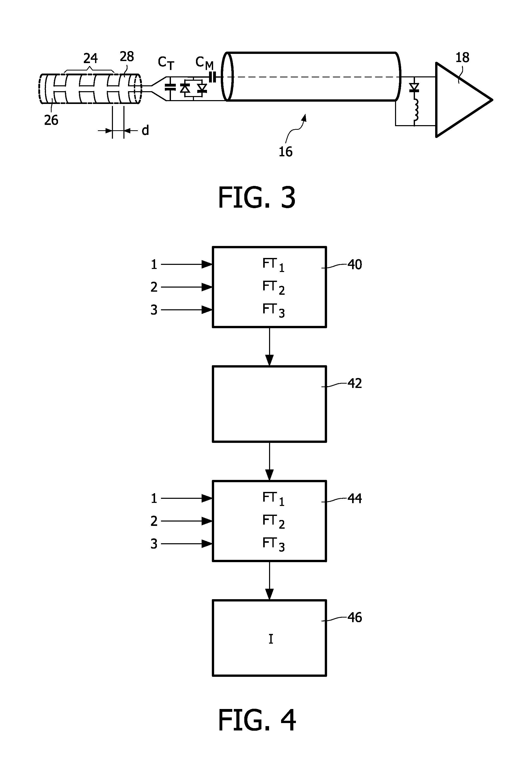
[0031]The system further comprises an endoscopic probe 16 which is inserted into the subject 14 via a small opening in the skin. Referring additionally to FIG. 3 of the drawings, an endoscopic probe 16 for use in a system according to an exemplary embodiment of the present invention comprises a tuned resonant circuit 18 mounted on the tip of the probe 16, which is capacitively coupled to the MRI scanner's amplifier / ...


PUM


Abstract

A resonance imaging (MRI) apparatus (10), comprising: one or more transmitting coils (12) for generating a static magnetic field within which a subject (14) can be positioned and a probe (16) for insertion into, and movement through, the subject (14). The probe (16) includes a tracking element (26,28) in the form of two loop coils and an imaging coil (24). Processing means (22) are provided for receiving spatially encoded signals from the loop coils (26,28) and from the imaging coil (24). The tracking signals from the loop coils (26,28) are decoded to determine the relative position of the probe (16) within an image volume and the image to be displayed as adjusted accordingly corresponding to the relative position of the probe (16). The image signals from the imaging coil (24) are also decoded to generate an image for display, and the image to be displayed is updated dynamically as the probe (16) is moved within the subject (14) based on successive sets of tracking signals received from the tracking element (26,38) and successive sets of spatially encoded signals received from the imaging coil (24).

Description

FIELD OF THE INVENTION[0001]This invention relates generally to Magnetic Resonance Imaging (MRI) and more specifically to a catheter-based MRI system with adaptive image quality, particularly but not necessarily exclusively suited to intravascular MR imaging.BACKGROUND OF THE INVENTION[0002]It is well known to use Magnetic Resonance Imaging (MRI) for interventional procedures, such as guiding a medical device in the form of a catheter through a vessel to a target within a subject's body. In a typical MRI system, a subject is placed within the radio-frequency coils of an MRI scanner and the coils of the scanner generate a very strong static magnetic field (e.g. 0.5 Tesla) which causes the hydrogen nuclei in the part(s) of the subject within the magnetic field to align themselves with the field. This primary magnetic field is then modified by three superimposed gradients, one for each of the x, y and z directions, so as to provide a spatial modulation of the field which can then be us...

Claims


Application Information

Patent Timeline
Patent Type & Authority Applications(United States)
IPC IPC(8): G01R33/48
CPCG01R33/287
Inventor ELGORT, DANIEL R.
Owner KONINKLIJKE PHILIPS ELECTRONICS NV
Why Eureka
Try Eureka