

Flexible locking and sealing device
- Summary
- Abstract
- Description
- Claims
- Application Information
AI Technical Summary
Benefits of technology
Problems solved by technology
Method used
Image

Examples
second embodiment
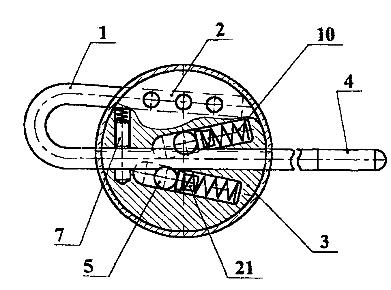
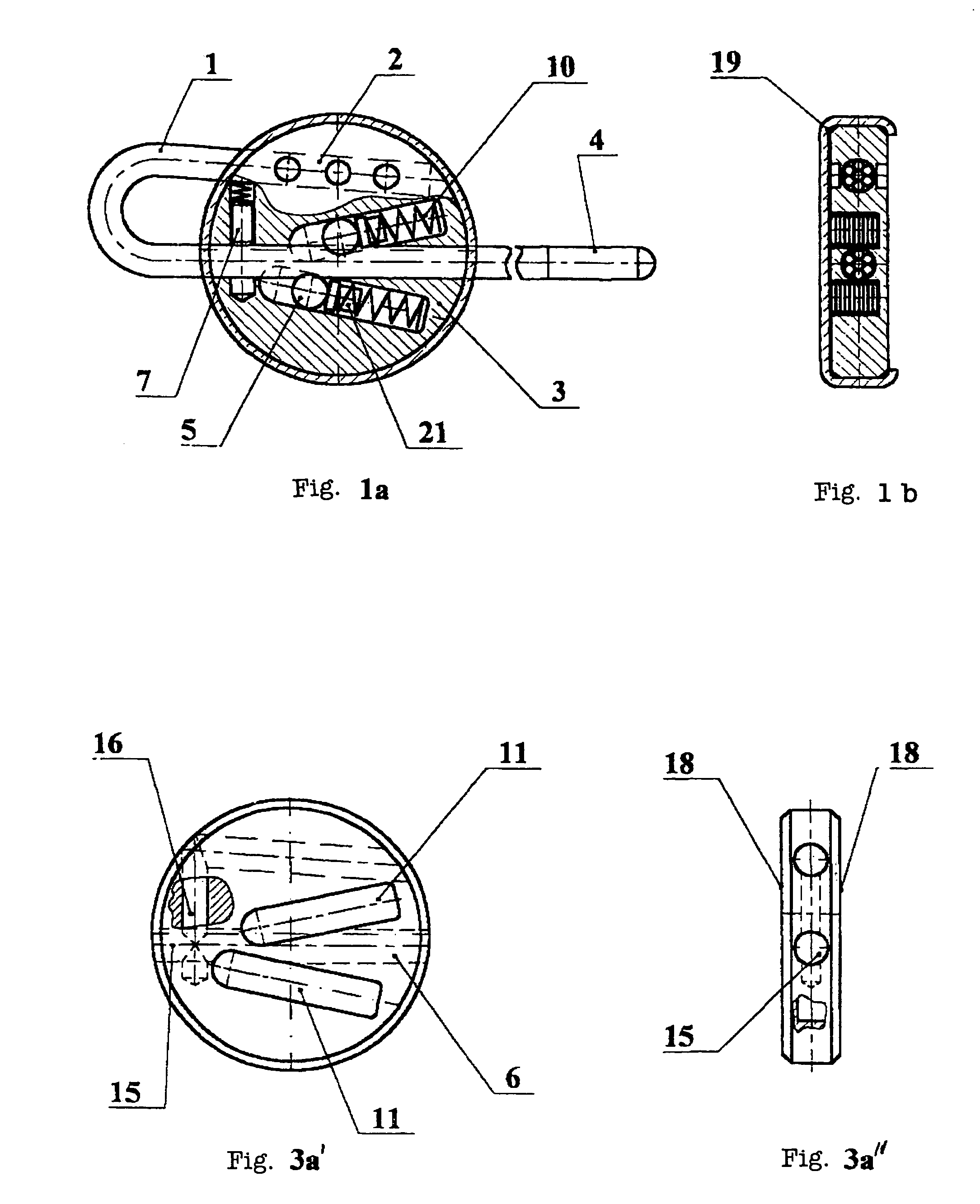
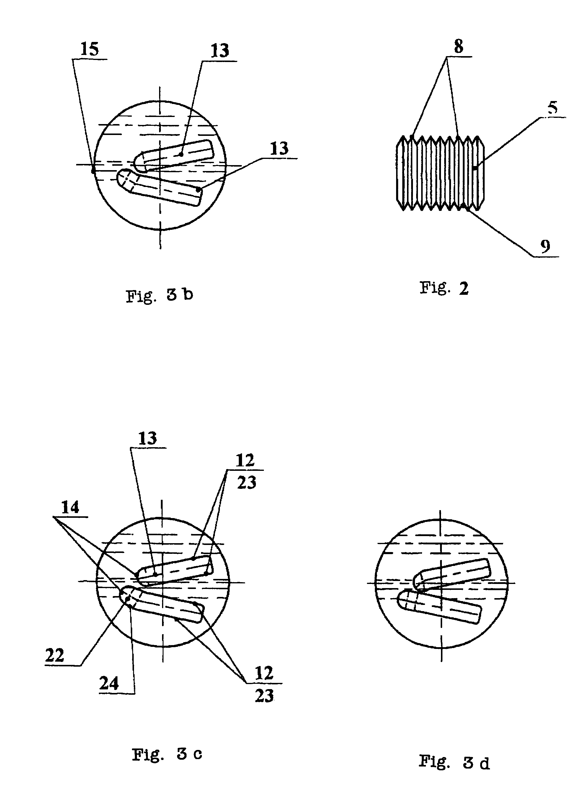
[0066]According to the invention, shown on FIGS. 4-6, 12 and 14 in a locked state with forming a loop, on FIG. 10—in line, a flexible locking and sealing device comprises a wire rope cut 1 which when locking passes through a channel 6 of a body 3 and is fixed by several spring-loaded rollers 5, disposed in the mounting seats, provided in the body 3. The mounting seats for the rollers 5 are made in the form of two longitudinal slots, which are disposed on two diametrically opposite sides of the through channel 6 and are able to communicate with the space of the through channel 6. Two longitudinal slots 11 have the stop end surfaces 14, which are offset with respect to each other and with respect to the input hole 15 of the body 3. Both slots 11 are inclined to the through channel 6 of the body 3 and the angles of their inclination are oriented to the input hole 15 of the body 3. The spring-loaded by the springs rollers 5 are disposed in the slots 11 able to rotate and move along the ...
first embodiment
[0087]According to the invention the flexible locking sealing device is used in the following way. Beforehand, in the mounting seats 11 in the body 3 the rollers 5 are arranged together with the springs 10 and the pushers 21, and are fixed there by means of the controller 17. During the locking operation the sharpened and optionally provided with the cap 34 end 4 of the wire rope cut 1 in inserted into the body 3 through its input hole 15, interacts with the end of the controller 17 and gradually pushes it out from the body 3. When the wire rope cut 1 passes through the body 3, at first one of the rollers 5, disposed closer to the input hole 15 of the body 3, interacts with the side surface of the wire rope cut 1, providing fast bond to the wire rope cut 1. Then the second roller 5 interacts with the side surface of the wire rope cut 1, already bonded to the first roller 5, making the final locking and tightening of the wire rope cut. The final tightening of the wire rope cut 1 is c...
PUM
 Abstract
Description
Claims
Application Information