
Emboli elimination apparatus

a technology of elimination apparatus and bubble trap, which is applied in the direction of liquid degasification, separation of dispersed particles, and separation of separation processes, etc., can solve the problems of negating the intended purpose of the bubble trap and negatively affecting the intended purpose of removing the bubbles from the fluid flow path, and achieves the effect of economical manufacture and assembly and simple design

Inactive Publication Date: 2007-10-09
WRIGHT DAVID W
View PDF6 Cites 99 Cited by
  • Summary
  • Abstract
  • Description
  • Claims
  • Application Information

AI Technical Summary

Benefits of technology

[0007]An apparatus for eliminating bubbles from a flow path of fluid is operable to eliminate the bubbles from the flow of fluid regardless of the orientation of the apparatus and regardless if the pressure within the flow path is less than the ambient atmospheric pressure. The apparatus has a body with a wall defining at least in part an enclosed chamber. The wall has a first opening providing fluid flow into the chamber and a second opening providing fluid flow out of the chamber. The wall has a vent allowing gas to pass outwardly from the chamber. An outlet tube extends from the second opening into the chamber and has an aperture located at a geometric center of the chamber. The aperture allows fluid within the chamber to enter the outlet tube and flow outwardly from the chamber through the second opening. With the chamber having fluid filling greater than half of the volume of the chamber, bubbles within the chamber are prevented from entering the outlet tube regardless of the orientation of the body. Accordingly, the performance of the apparatus is not reliant on remaining in any certain orientation.
[0008]Some of the objects, features and advantages of this invention include, by way of example and without limitations, providing an apparatus for removing bubbles from a flow of blood regardless of the orientation of the apparatus, preventing bubbles from entering an outlet flow of blood from the apparatus, reducing the potential sources for bubble entry into the output flow of blood from the apparatus, and is of relatively simple design and economical manufacture and assembly.

Problems solved by technology

Otherwise, if the bubble trap is skewed from its proper orientation, the bubbles within the flow of fluid can not be removed from the flow of fluid, thereby negating the purpose of the bubble trap.
These devices, though largely effective in their purpose of removing bubbles from the flow of fluid, potentially allow air to ingress into the fluid flow path if the pressure within the chamber is less than the ambient pressure, thereby negatively impacting their intended purpose of removing bubbles from the fluid flow path.

Method used


Image

  • Emboli elimination apparatus
  • Emboli elimination apparatus
  • Emboli elimination apparatus

Examples


Embodiment Construction

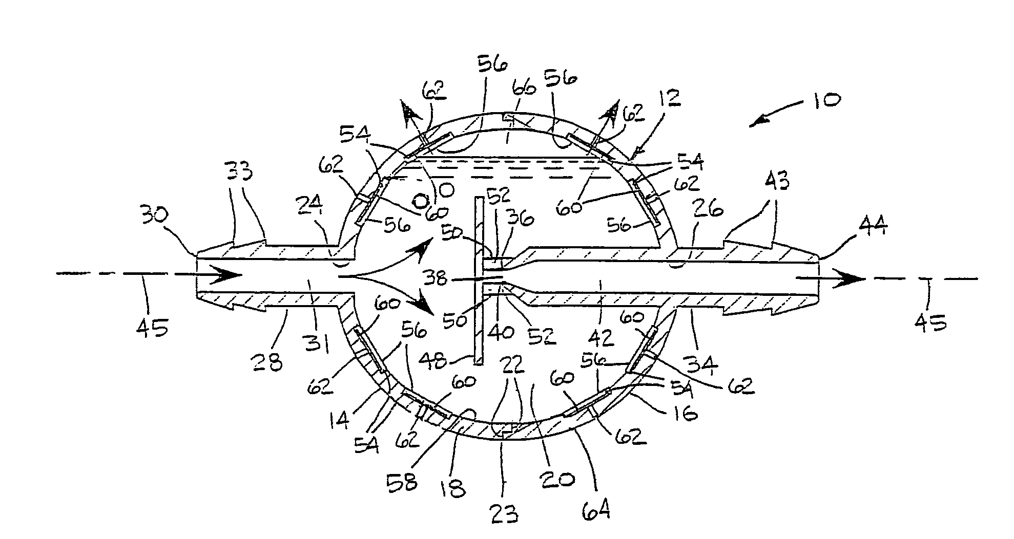
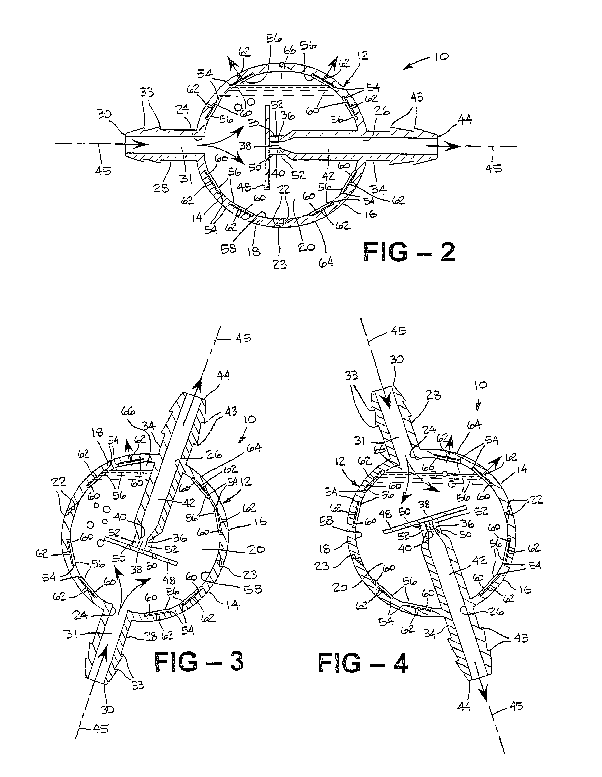
[0028]Referring in more detail to the drawings, FIG. 1 illustrates an apparatus for eliminating gas, typically in the form of emboli or air bubbles, from a flow of fluid, such as blood or profusion solution, for example, generally at 10. The apparatus 10 is suitable for use in any application requiring the elimination of gas bubbles from fluid, such as, for example, during hemodialysis, a blood transfusion, obtaining a sample of blood, while obtaining blood from a donor, or any other situation requiring the transfer of fluid through a blood or fluid line 11.

[0029]The apparatus 10 has a body 12 that is generally spherical in shape and preferably has a pair of mating halves 14, 16, such that when the halves 14, 16 are joined to one another they form a substantially continuous wall 18 defining a chamber 20 therein. Preferably, each half 14, 16 has a stepped perimeter 22 to facilitate mating engagement between the two halves 14, 16 along a joint 23 (FIGS. 2-4). The two halves 14, 16 are...


PUM

PropertyMeasurementUnit
Pressureaaaaaaaaaa
Flow rateaaaaaaaaaa
Diameteraaaaaaaaaa

Abstract

An apparatus has a body with a wall defining at least in part an enclosed chamber. The wall has a first opening providing fluid flow into the chamber and a second opening providing fluid flow out of the chamber. The wall has a vent allowing gas to pass outwardly from the chamber. An outlet tube extends from the second opening into the chamber and an aperture. The aperture allows fluid within the chamber to enter the outlet tube and flow outwardly from the chamber through the second opening. Bubbles within the chamber are prevented from entering the outlet tube regardless of the orientation of the body.

Description

REFERENCE TO CO-PENDING APPLICATION[0001]This application claims the benefit of U.S. Provisional Application No. 60 / 524,824, filed Nov. 25, 2003.BACKGROUND OF THE INVENTION[0002]1. Field of the Invention[0003]This invention relates generally to bubble traps for eliminating gas bubbles from a flow of blood or transfusate through a fluid line.[0004]2. Related Art[0005]Conventionally, bubble traps comprise a wall defining a chamber, with an inlet providing fluid flow into the chamber and an outlet providing fluid flow out of the chamber. Generally, the inlet and outlet are separated by an expanded chamber volume to establish a low velocity flow path for the fluid traveling between the inlet and outlet. As the fluid flows from the inlet to the outlet, the bubbles within the volume of fluid generally rise to a gas dome within the chamber to be vented from the chamber. Conventionally, bubble traps must be maintained in a specific orientation to enable the bubble trap to function effective...

Claims


Application Information

Patent Timeline
IPC IPC(8): B01D19/00
CPCA61M1/3627B01D19/0042A61M5/36A61M5/385
Inventor WRIGHT, DAVID W.
Owner WRIGHT DAVID W
Features
  • Generate Ideas
  • Intellectual Property
  • Life Sciences
  • Materials
  • Tech Scout
  • Unparalleled Data Quality
  • Higher Quality Content
  • 60% Fewer Hallucinations
Learn More