
Method and apparatus for in-situ detection and isolation of aircraft engine faults

a technology for aircraft engines and fault isolation, applied in the direction of instruments, testing/monitoring control systems, nuclear elements, etc., can solve the problems of accelerating deterioration, high safety risks, and failures of small components and other operating faults

Active Publication Date: 2007-10-09
GENERAL ELECTRIC CO
View PDF20 Cites 85 Cited by
  • Summary
  • Abstract
  • Description
  • Claims
  • Application Information

AI Technical Summary

Benefits of technology

Enables the early detection and timely maintenance of small faults, reducing safety risks and operational costs while extending the engine's operating life by distinguishing small faults from larger ones and isolating their causes.

Problems solved by technology

However, as with all machinery, small component failures and other operating faults may occur, owing to material failures, environmental disturbances, and normal deterioration during the operating life of an aircraft engine.
Having faults go undetected and without compensating control actions can risk further damage and may accelerate deterioration, leading to higher safety risks.
Similarly, when engine faults are detected by imprecise means and with high levels of uncertainty, operators are often obliged to take the most conservative measures, which typically involve aborting a takeoff or shutting down an engine during flight.
There is no systematic procedure for taking into account the behavior of the overall system by using a system model in concert with all of the available sensors.
This causes current methods to be unable to detect faults until they reach a relatively large magnitude.

Method used


Image

  • Method and apparatus for in-situ detection and isolation of aircraft engine faults
  • Method and apparatus for in-situ detection and isolation of aircraft engine faults
  • Method and apparatus for in-situ detection and isolation of aircraft engine faults

Examples


Embodiment Construction

[0019]The present invention will be explained in further detail by making reference to the accompanying drawings, which do not limit the scope of the invention in any way.

[0020]Modern aircraft engines employ full-authority digital controls, which make use of sensors deployed throughout the engine. This invention describes how these same sensor measurements can be used to monitor the health of the engine, including its actuators and the sensors themselves. By using a system model with available sensors, this invention is able to isolate the cause of the engine event when it occurs. Moreover, this invention is able to distinguish small faults from large faults. Along with the safety advantages of being able to distinguish small faults from larger faults, the ability to detect small faults early enables more timely engine maintenance, which reduces costs and extends the operating life of the engine.

[0021]The invention will now be taught using various exemplary embodiments. Although the...


PUM


Abstract

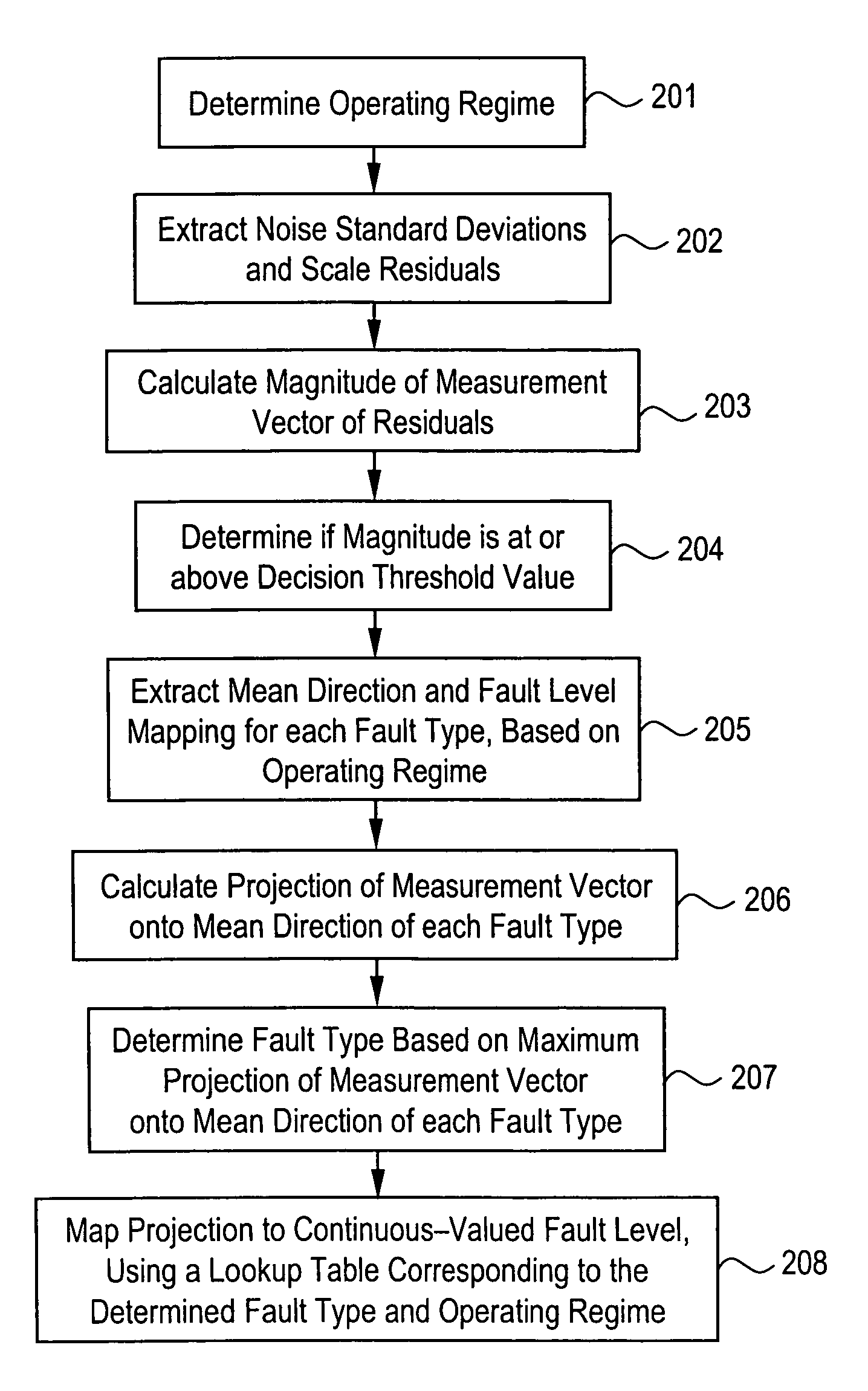
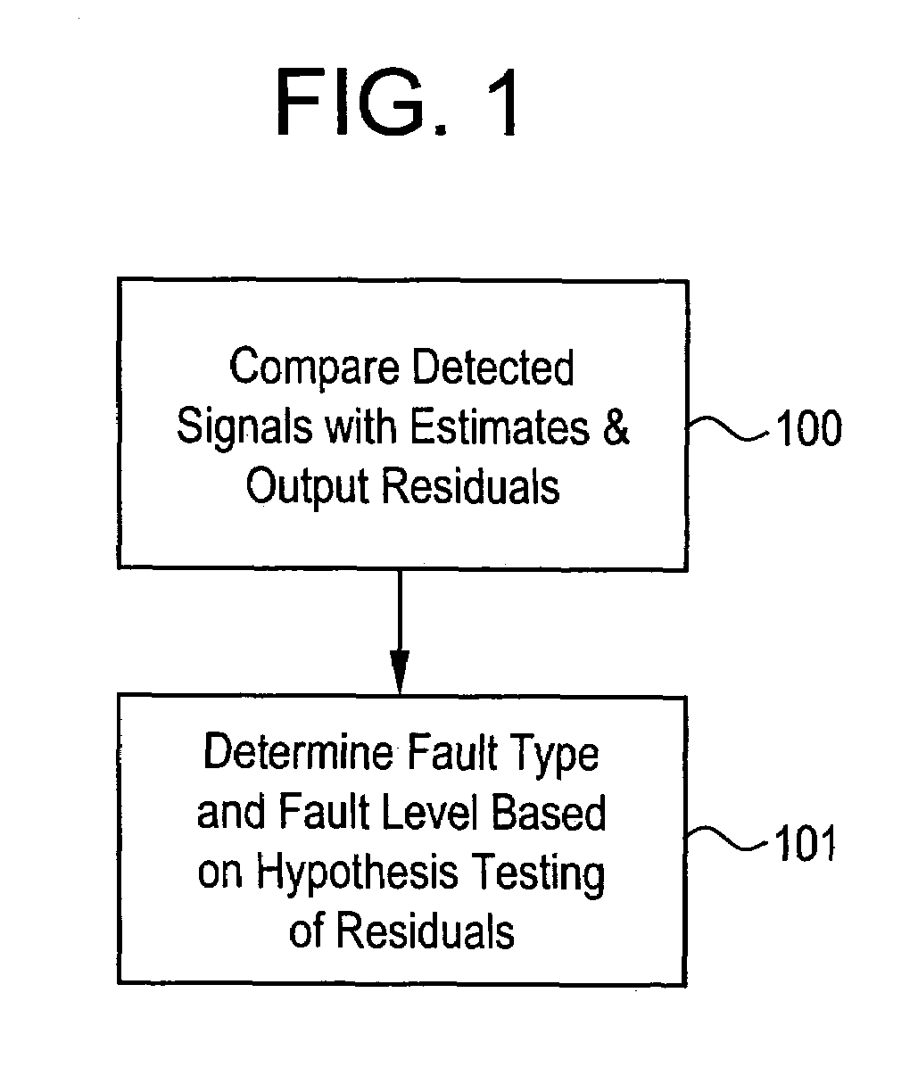
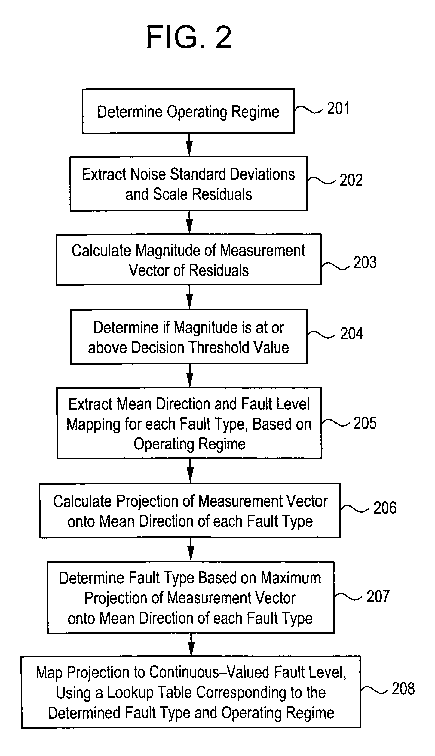
A method for performing a fault estimation based on residuals of detected signals includes determining an operating regime based on a plurality of parameters, extracting predetermined noise standard deviations of the residuals corresponding to the operating regime and scaling the residuals, calculating a magnitude of a measurement vector of the scaled residuals and comparing the magnitude to a decision threshold value, extracting an average, or mean direction and a fault level mapping for each of a plurality of fault types, based on the operating regime, calculating a projection of the measurement vector onto the average direction of each of the plurality of fault types, determining a fault type based on which projection is maximum, and mapping the projection to a continuous-valued fault level using a lookup table.

Description

STATEMENT REGARDING FEDERALLY SPONSORED RESEARCH & DEVELOPMENT[0001]This invention was made with Government support under contract number NAS3-01135 awarded by the National Aeronautics and Space Administration (NASA). The Government has certain rights in the invention.BACKGROUND OF THE INVENTION[0002]This invention relates to detecting and classifying faults in an operating machine, and more particularly to detecting and classifying faults in an operating aircraft engine using an Extended Kalman Filter architecture.[0003]Aircraft engines must maintain the highest achievable levels of reliability, because of their extreme safety-critical nature and because the vehicles powered by these engines represent enormous investments in resources. However, as with all machinery, small component failures and other operating faults may occur, owing to material failures, environmental disturbances, and normal deterioration during the operating life of an aircraft engine.[0004]Having faults go und...

Claims


Application Information

Patent Timeline
Patent Type & Authority Patents(United States)
IPC IPC(8): G06F15/00G05B13/02G01M13/00G01M99/00
CPCG05B23/0281G05B23/0254
Inventor BONANNI, PIERINO GIANNIBRUNELL, BRENT JEROME
Owner GENERAL ELECTRIC CO
Learn More