
Fault information collection program and apparatus

Inactive Publication Date: 2007-10-09
FUJITSU LTD
View PDF8 Cites 72 Cited by
  • Summary
  • Abstract
  • Description
  • Claims
  • Application Information

AI Technical Summary

Benefits of technology

[0016]The present invention was created in view of the above circumstances, and an object thereof is to provide fault information collection program and apparatus capable of accurately determining redundancy of information related to an identical fault even in cases where information indicating the state of an identical target of monitoring is received from a plurality of devices.

Problems solved by technology

Since daily transactions are thus deeply involved with the network, damage to the transactions is greater than ever if fault occurs in the network.
In the case of monitoring a large-scale network constituted by a plurality of small-scale networks, numerous engineers who take charge of network management are needed if the engineers are assigned to the respective small-scale networks for monitoring, which leads to inefficiency.
When a fault has occurred on the networks, no measures can be taken unless information indicating the fault reaches the server.
In the system in which paths are switched in case of fault occurrence, however, a problem arises in that no fault information reaches the server during the period after a fault occurs in the original path until the paths are switched following confirmation of the fault.
However, with this method, the management server is unable to determine whether an identical fault has occurred a plurality of times or a single fault has been notified in parallel.
For certain types of fault on the network, different measures need to be taken depending on the frequency of occurrences of fault, and therefore, such parallel notification can confuse the system administrator.
In this case, however, it is difficult to affix identical identification information to telegrams which are output in parallel from different supervisory servers.
For example, in the case of monitoring a network state by polling, supervisory servers differ from each other in polling timing, so that a fault caused by an identical event is detected at different times. As a result, the receiving side is unable to determine whether or not a received message is based on the same fault (whether the received message is a redundant message) by merely checking the fault detection time.

Method used


Image

  • Fault information collection program and apparatus
  • Fault information collection program and apparatus
  • Fault information collection program and apparatus

Examples


Embodiment Construction

[0029]Embodiments of the present invention will be hereinafter described with reference to the drawings.

[0030]First, the invention applied to the embodiments will be outlined, and then the embodiments will be described in detail.

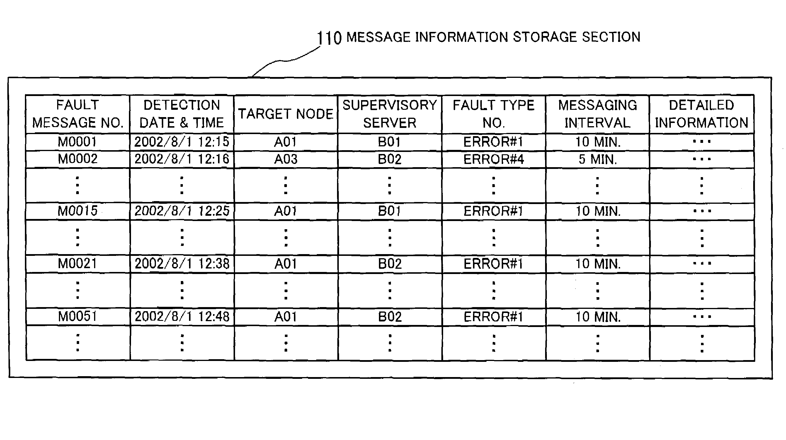
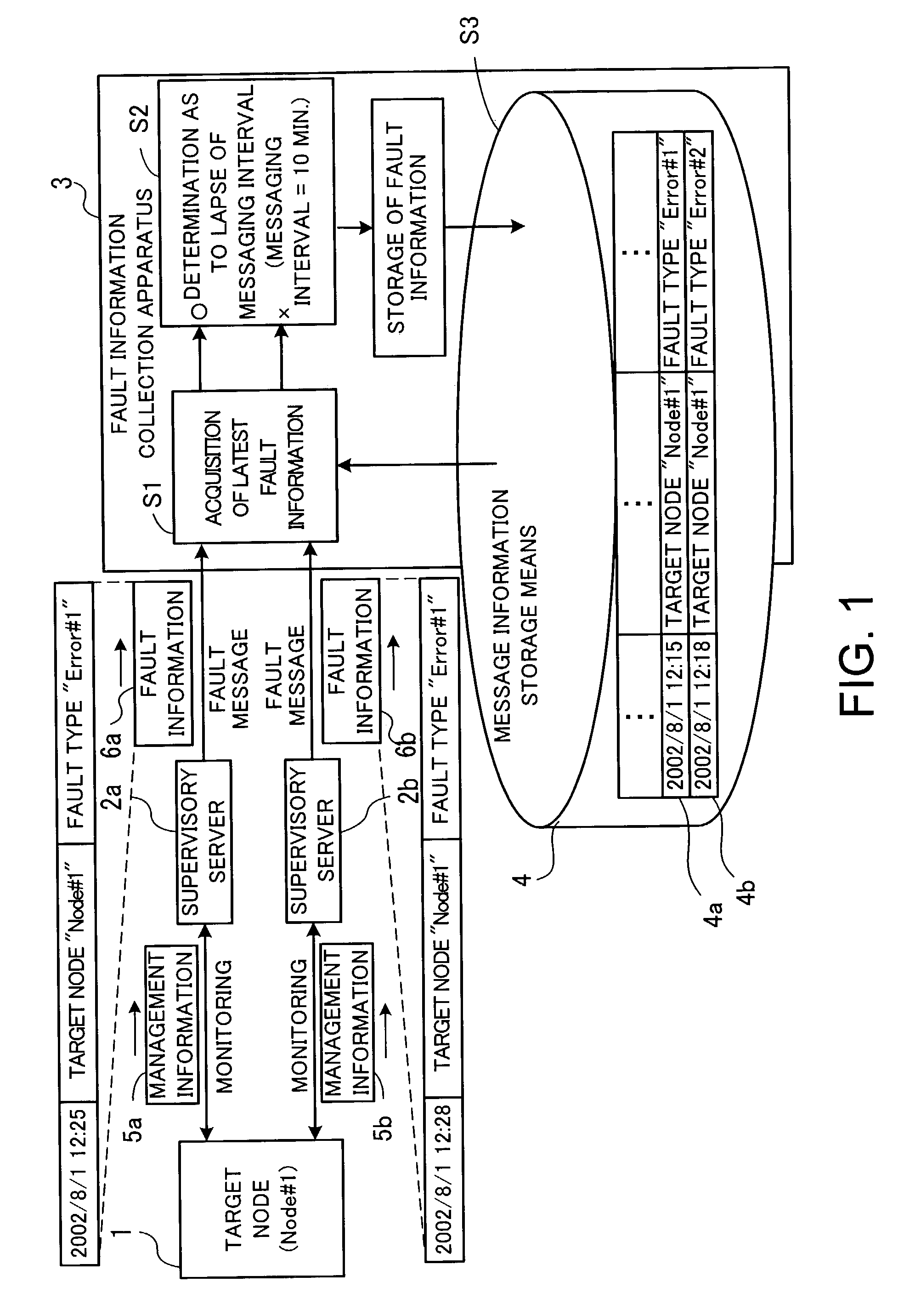
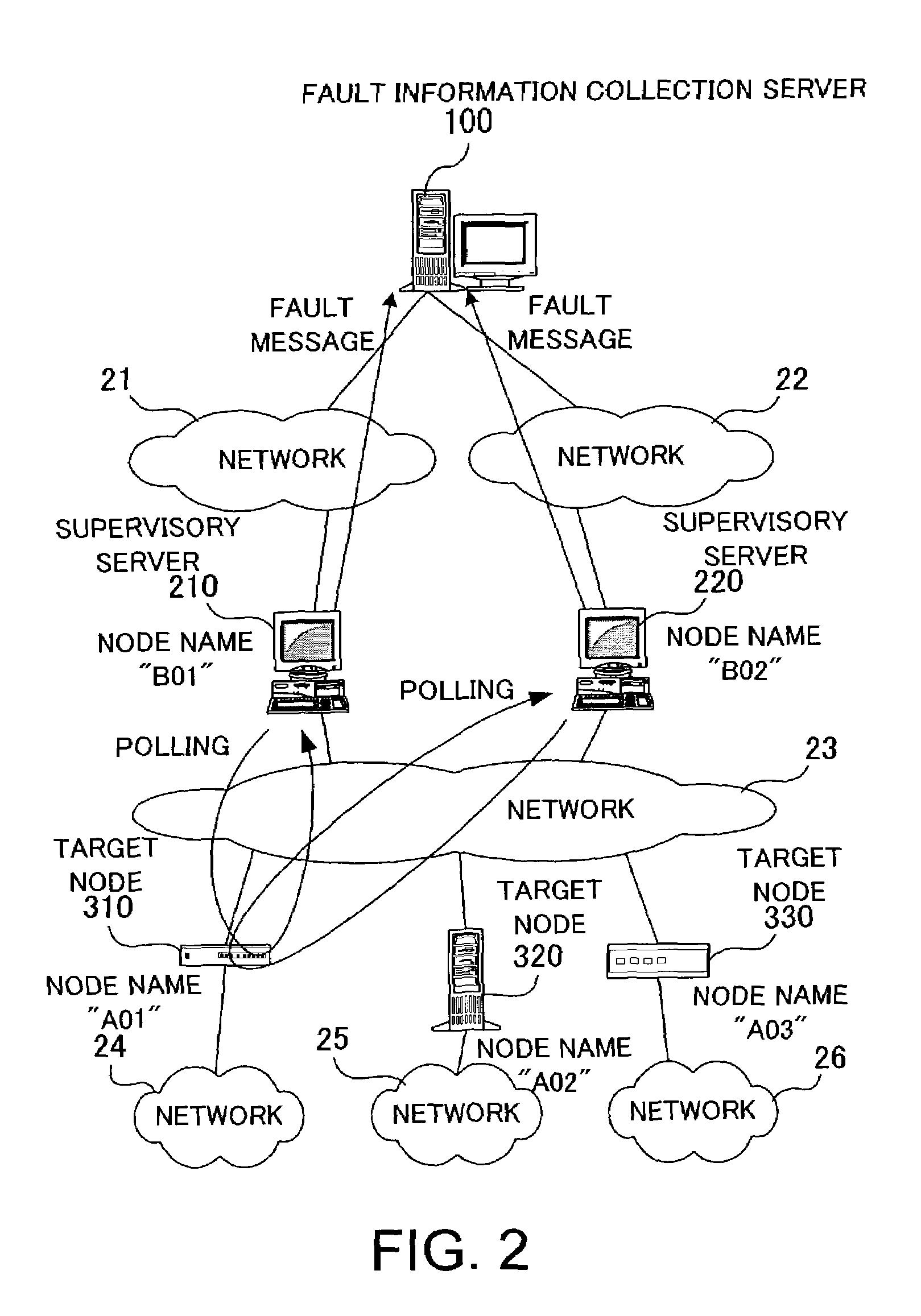
[0031]FIG. 1 is a conceptual diagram illustrating the invention applied to the embodiments. According to the present invention, a plurality of supervisory servers 2a, 2b are connected through a network to a node 1 which is a target of monitoring. In the following, it is assumed that the target node 1 has the node name “Node#1”. The supervisory servers 2a, 2b are individually connected to a fault information collection apparatus 3 through respective networks. The fault information collection apparatus 3 has a message information storage means 4 for storing information about faults. The message information storage means 4 stores a plurality of past fault information 4a, 4b including detection dates and times of faults.

[0032]The supervisory server 2a monitors t...


PUM


Abstract

A fault information collection program capable of accurately determining redundancy of information related to an identical fault even in cases where information indicating the same fault of the same target of monitoring is received from multiple devices. When new fault information including fault detection date and time is input, the latest fault information indicating a fault related to the fault identical with that of the new fault information is acquired from a message information storage means storing a plurality of past fault information including detection dates and times of faults. It is then determined whether or not a predetermined messaging interval has elapsed since the fault detection date and time indicated by the latest fault information until the fault detection date and time indicated by the new fault information. If the messaging interval has elapsed, the new fault information is stored in the message information storage means as valid fault information.

Description

BACKGROUND OF THE INVENTION[0001](1) Field of the Invention[0002]The present invention relates to fault information collection program and apparatus for monitoring network environments, and more particularly, to fault information collection program and apparatus capable of receiving network state-indicative messages in a redundant configuration.[0003](2) Description of the Related Art[0004]With the recent progress of computerization of business transactions, many corporations have their own in-house computer networks. It is, therefore, generally the case that documents created for transactions, for example, are distributed through the network to the persons concerned, with the use of functions such as electronic mail and groupware.[0005]Since daily transactions are thus deeply involved with the network, damage to the transactions is greater than ever if fault occurs in the network. Accordingly, there has been a demand that the network state be monitored and that when a fault has occ...

Claims


Application Information

Patent Timeline
IPC IPC(8): G06F11/00H04L69/40G06F13/00
CPCH04L12/2602H04L41/0604H04L43/00H04L41/069H04L43/0817
Inventor CHUJO, MIKIYA
Owner FUJITSU LTD
Features
  • Generate Ideas
  • Intellectual Property
  • Life Sciences
  • Materials
  • Tech Scout
  • Unparalleled Data Quality
  • Higher Quality Content
  • 60% Fewer Hallucinations
Learn More