
Methods of generator rotor removal in a combined-cycle stag application

a combined-cycle stag and generator technology, applied in the direction of machines/engines, machine supports, manufacturing tools, etc., can solve the problem of not being able to remove the generator field axially, and achieve the effect of reducing plant downtime, minimizing the lifting capacity required, and saving plant costs

Inactive Publication Date: 2007-10-16
GENERAL ELECTRIC CO
View PDF3 Cites 9 Cited by
  • Summary
  • Abstract
  • Description
  • Claims
  • Application Information

AI Technical Summary

Benefits of technology

This method reduces plant downtime, minimizes lift capacity requirements, and saves costs by enabling generator stator movement within the foundation, allowing for efficient rotor removal and reinstallation without interference from the turbines.

Problems solved by technology

With the three main components of the combined-cycle system secured to the foundation, however, and in axial alignment one with the other, it is not possible to remove the generator field axially due to the lack of clearance with respect to the turbines at opposite ends of the generator.
However, because the generator is an electromagnetic component, it is not possible to split the generator rotor and casing at the centerline and lift the generator rotor from the generator in a vertical direction.

Method used


Image

  • Methods of generator rotor removal in a combined-cycle stag application
  • Methods of generator rotor removal in a combined-cycle stag application
  • Methods of generator rotor removal in a combined-cycle stag application

Examples


Embodiment Construction

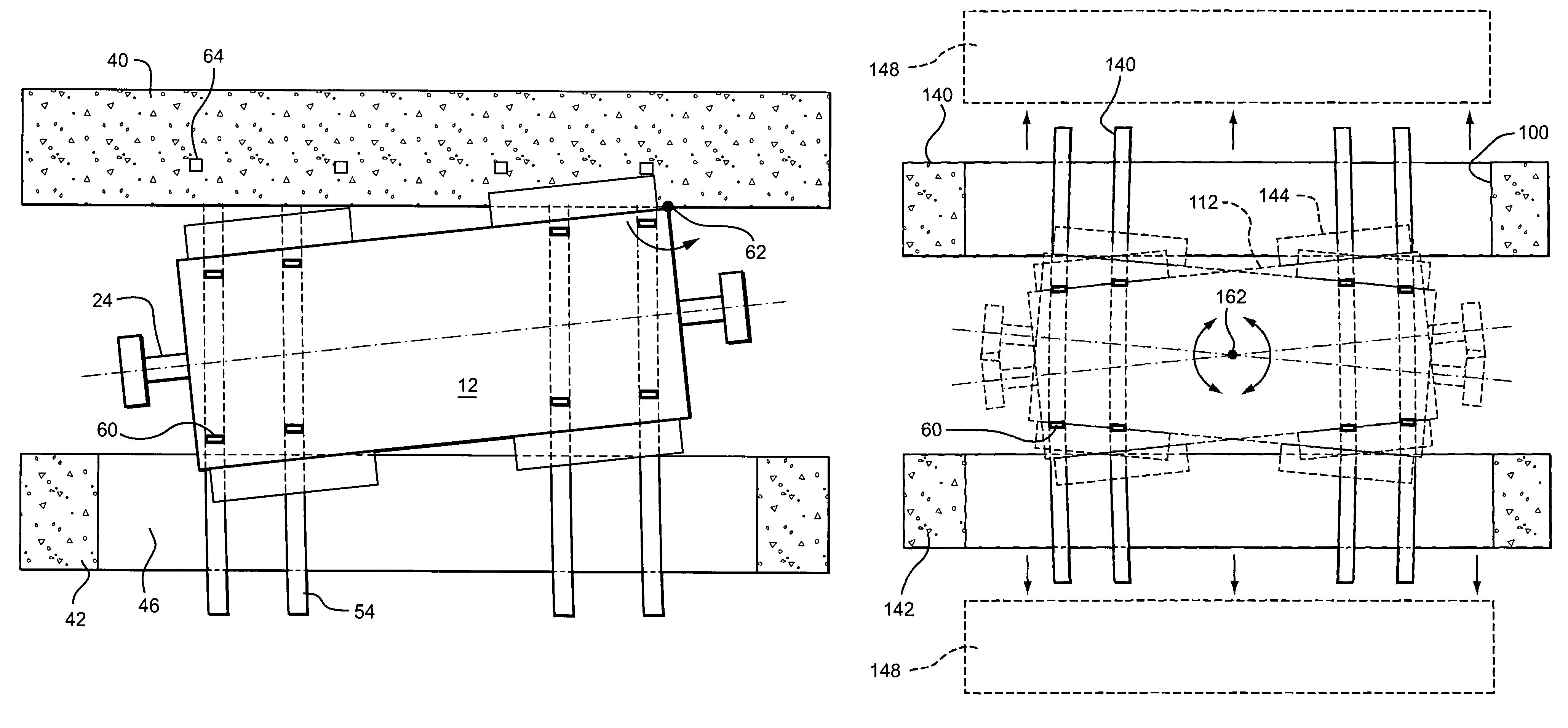
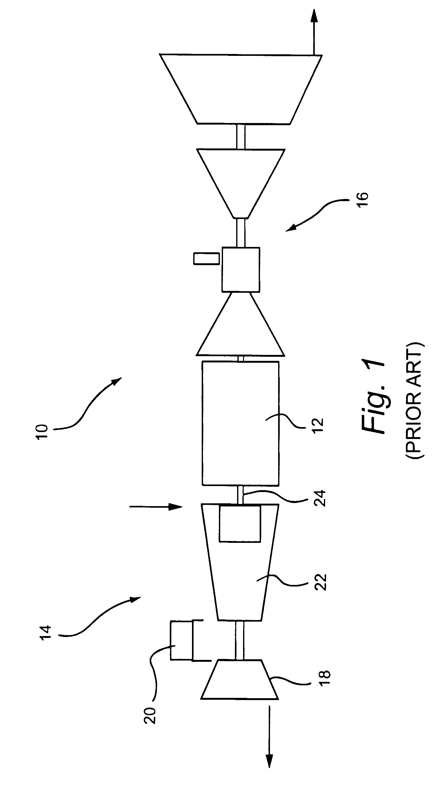
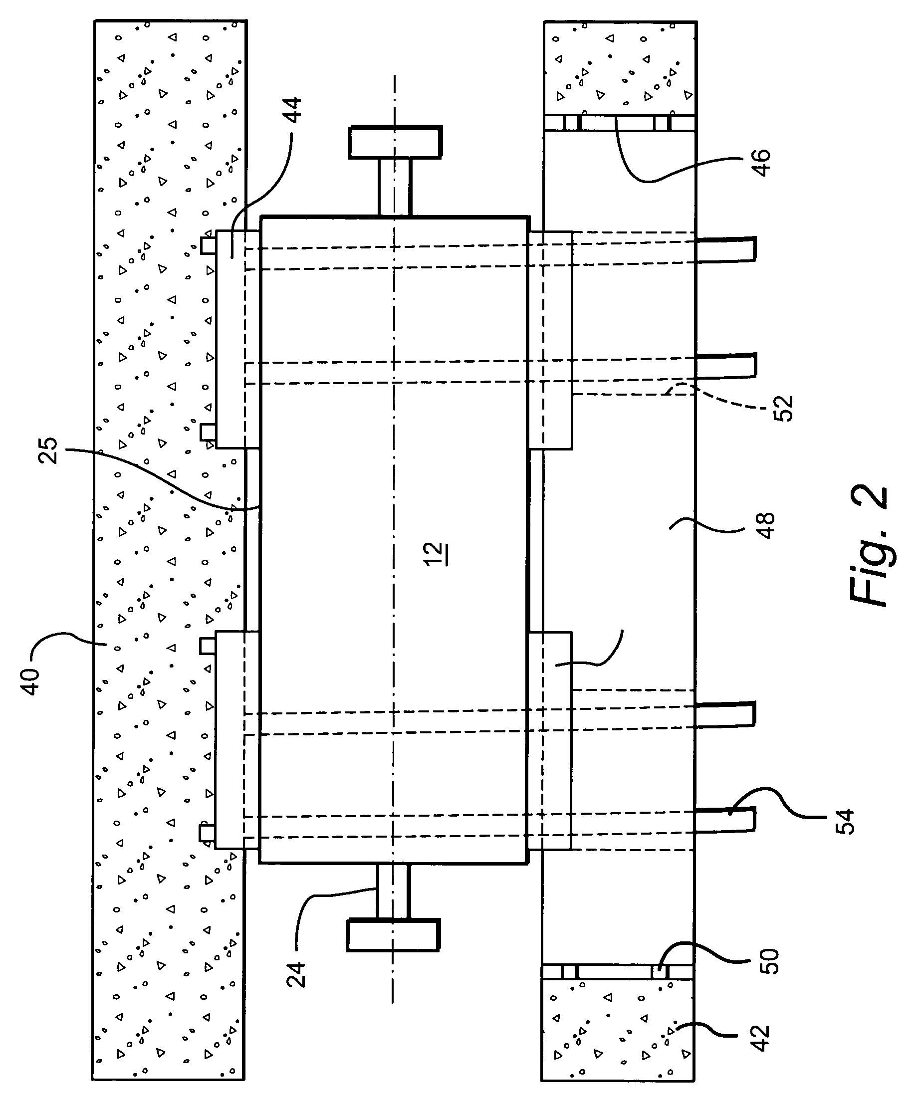
[0015]Referring now to the drawings, particularly to FIG. 1, there is illustrated a STAG (steam turbine and gas turbine) combined-cycle system, generally designated 10, including a generator 12 in axial alignment with a gas turbine, generally designated 14, and a steam turbine, generally designated 16. As illustrated, the gas turbine 14 includes a compressor 18, a plurality of combustors 20 and a gas turbine section 22 for driving a rotor axially coupled to the generator rotor 24 within a generator housing 25 (FIG. 4). The generator rotor at the opposite end of the generator 12 is coupled to a series of high, intermediate and low pressure steam turbines which utilize the high temperature exhaust from the gas turbine and a heat recovery steam generator to convert the gas turbine exhaust into useful steam for the bottoming portion of the combined cycle. It will be appreciated that the generator rotor 24 is axially aligned with and coupled to the rotors of both the gas the steam turbin...


PUM

PropertyMeasurementUnit
electrical poweraaaaaaaaaa
lengthaaaaaaaaaa
radiusaaaaaaaaaa

Abstract

Support feet of a generator are mounted on foundation columns spaced laterally one from the other, with one column having a block in a recess for receiving the feet on one side of the generator. Guides on a radius and supported by the generator foundation extend through notches on the underside of the block. To locate an end of the generator displaced horizontally from the turbines, the generator is unloaded from the foundation and the block is removed. The generator is then loaded onto the guides and pivoted about a vertical axis to locate at least one end out of alignment with the axis of the turbines enabling removal of the generator rotor in an axial direction.

Description

BACKGROUND OF THE INVENTION[0001]The present invention relates to a method of removing the generator rotor from an aligned gas turbine-generator-steam turbine configuration for maintenance and returning the generator to useful service in the aligned gas turbine-generator-steam turbine configuration.[0002]A gas turbine, generator and steam turbine are typically axially aligned one with the other with the generator located between the gas and steam turbines whereby the turbines drive the generator rotor to produce electrical power. This configuration is known as a STAG (steam and gas) combined-cycle system. In the STAG combined-cycle system, it will be appreciated that the opposite ends of the generator are mechanically coupled to the gas and steam turbines, respectively. The components of these systems are generally mounted on foundations prepared for supporting these large system components. Typically, the generator rotor, i.e., the generator field, must be removed from the generato...

Claims


Application Information

Patent Timeline
Patent Type & Authority Patents(United States)
IPC IPC(8): B23P19/00B23P6/00F02C1/00F01D25/28F16M5/00H02K15/00
CPCF01D25/285F16M5/00H02K15/0006Y10T29/49819Y10T29/4973Y10T29/49318Y10T29/49822H02K15/00H02K15/02
Inventor ASHAR, SIDDHARTH NAVINCHANDRABONNER, THOMASBRADT, RICHARD ALLENWAGNER, THOMAS ARTHURYAGIELSKI, JOHN RUSSELL
Owner GENERAL ELECTRIC CO
Learn More