Multi-clarity lenses

a technology of clarity and lens, applied in the field of multi-clarity lenses, can solve the problems of incandescent bulbs producing considerable heat, inability to achieve the effect of reducing the amount of incandescent nightlight, and affecting the rate at which active materials are diffused,

Inactive Publication Date: 2007-10-16
SC JOHNSON & SON INC
View PDF600 Cites 39 Cited by
  • Summary
  • Abstract
  • Description
  • Claims
  • Application Information

AI Technical Summary

Problems solved by technology

For example, incandescent bulbs produce considerable heat.
When incandescent nightlights are used in connection with a diffuser of volatile active material, the heat generated by the incandescent nightlight tends to affect the rate at which the active material is diffused.
Thus, when the nightlight is turned on, the active material may, for example, diffuse too quickly.
Also, because of the added heat, it is difficult to regulate the rate at which the active material is diffused.
Another disadvantage of using incandescent bulbs as nightlights is that the bulbs tend to consume relatively large amounts of energy.
Since nightlights are often left on for extended periods of time in multiple rooms of a house, this energy consumption may be a significant consideration.
These techniques, however, have yielded only minor reductions in heat emission and energy consumption, and come at a cost to performance of the nightlight.
Another problem with conventional diffusers is that the diffusers do not make effective use of lighting elements.
A still further problem is that conventional diffusers are limited in use to locations where wall sockets are already exist.
Wall sockets are often located in places that are less than ideal for placement of diffusers, such as near the floor, in a corner, etc.
This limitation on the location of diffusers is even more problematic for diffusers that have a lighting element or display, since the diffuser often cannot be located in a user's line of sight, thereby limiting the effectiveness of the lighting element.
Yet another problem is that conventional diffusers typically do not have suitable controllability for varying the emission of light and / or fragrance.
In particular, such diffusers seldom have fragrance dispensers that are easily and precisely adjustable to vary a fragrance intensity or diffusion rate.

Method used


Image

  • Multi-clarity lenses
  • Multi-clarity lenses
  • Multi-clarity lenses

Examples


Embodiment Construction

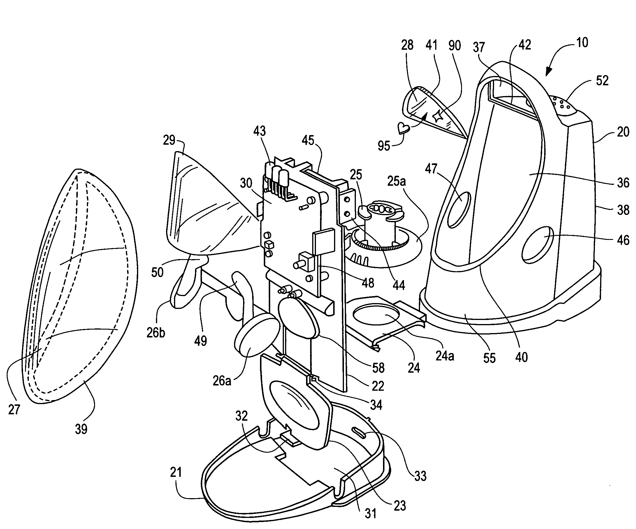
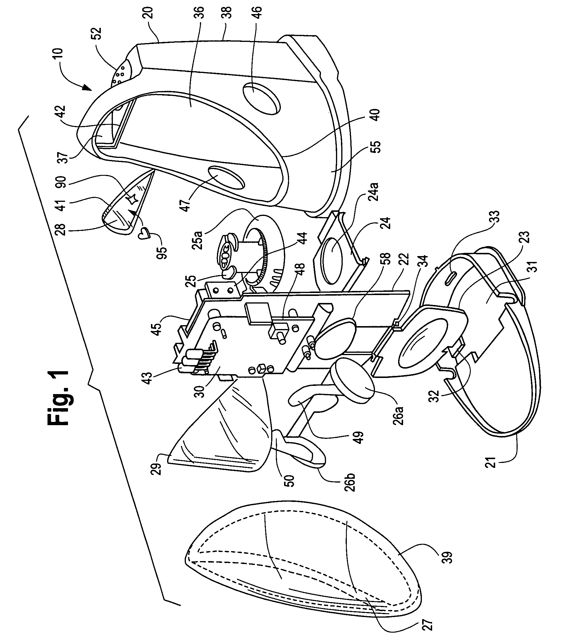
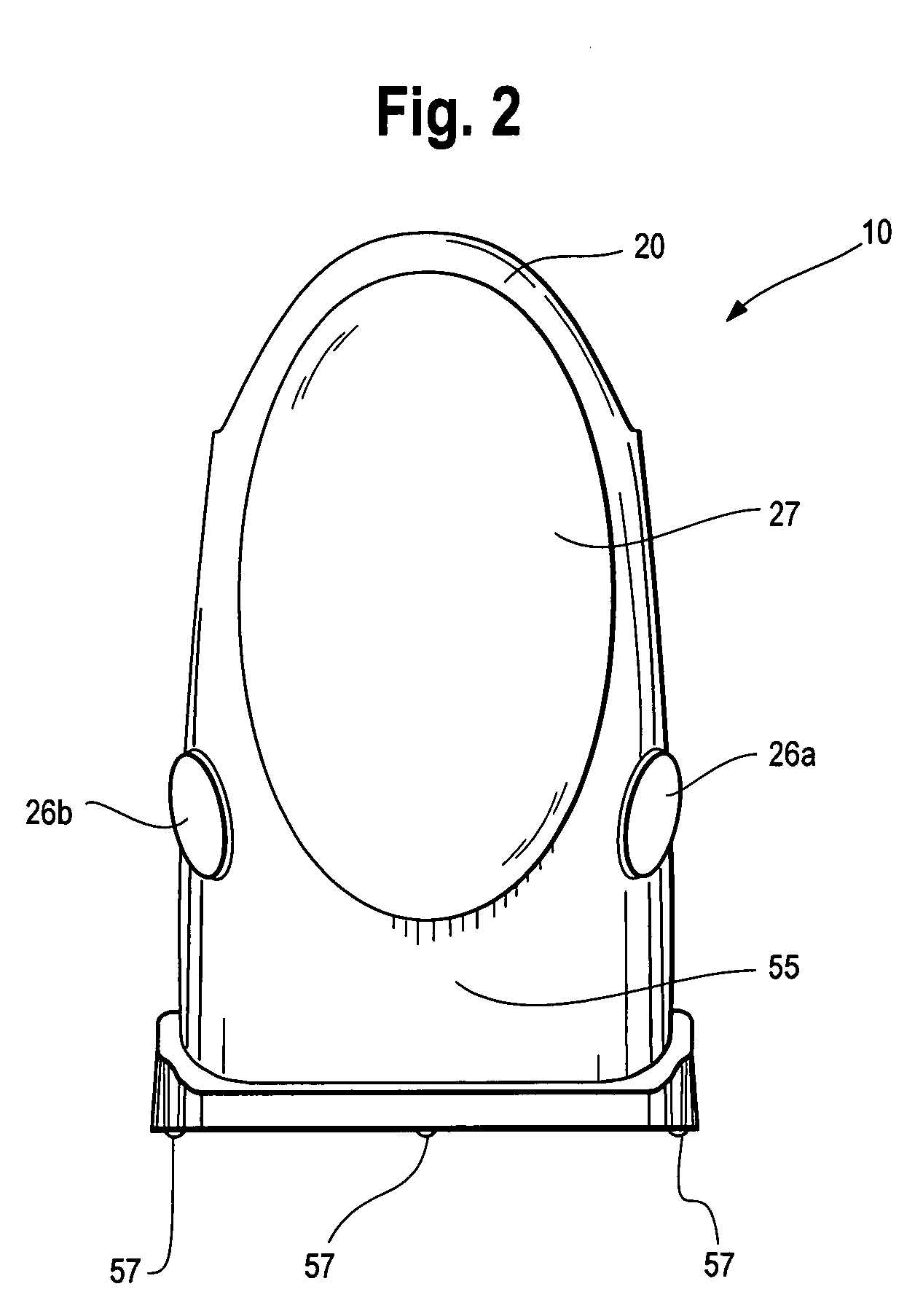
[0042]The present invention is directed toward apparatuses, devices, methods, kits, programs, and combinations to disperse and / or project light. While the present invention may be embodied in many different forms, several specific embodiments are discussed herein with the understanding that the present disclosure is to be considered only as an exemplification of the invention and is not intended to limit the invention to the embodiments illustrated. For example, in one embodiment of the present invention where a light effect of glowing, diffused, and projected light is desired, one lens is provided that has a section or portion that diffuses light in one section of the lens and is substantially clear in another section to allow substantially all the light to pass through the lens. In other embodiments to obtain the same effect, one or more lenses diffuse light while one or more other lenses are clear to allow substantially all the light to pass through the lens(es).

[0043]A lens of t...


PUM


Abstract

The present invention is directed toward apparatuses, devices, methods, kits, programs, and combinations to disperse and / or project light. For example, in one embodiment of the present invention where a light effect of glowing, diffuse, and projected light is desired, one lens is provided that diffuses light in one section of the lens and is substantially clear in another section to allow substantially all the light to pass through the lens. In other embodiments to obtain the same effect, one or more lenses diffuse light while one or more other lenses are clear to allow substantially all the light to pass through the lens.

Description

CROSS REFERENCE TO RELATED APPLICATIONS[0001]Not applicableREFERENCE REGARDING FEDERALLY SPONSORED RESEARCH OR DEVELOPMENT[0002]Not applicableSEQUENTIAL LISTING[0003]Not applicableBACKGROUND OF THE INVENTION[0004]1. Field of the Invention[0005]The invention generally relates to multi-clarity lens that diffuse and / or project a light source.[0006]2. Description of the Background of the Invention[0007]Lenses that diffuse light are known in the art. Devices that incorporate lenses are also known. One such device is a lighting unit for use with common household lighting fixtures that uses an illumination system near a wall or surface for creating an image of light thereon by passing radiant light through a convergent refracting lens. The lens in one instance is decorative in shape and embellished with etched, drawn, painted or applied designs for projecting the image.[0008]Other devices that project light are nightlights that have a neon lamp or a number of light-emitting diodes (LED's) ...

Claims


Application Information

Patent Timeline
Patent Type & Authority Patents(United States)
IPC IPC(8): F21V33/00F24F6/08
CPCA61L9/037A61L2209/12
Inventor THUOT RANN, RAECHELL MARIADANCS, IMRE J.TRENT, JOHN S.
Owner SC JOHNSON & SON INC
Why Eureka
Try Eureka