Power terminal block

a power terminal and block technology, applied in the field of power terminal blocks, can solve the problems of increasing the difficulty of connecting wires and user manipulation, and achieve the effects of facilitating replacement, facilitating connection or installation, and simplifying the electrical installation process

Active Publication Date: 2007-10-16
AMERICA POWER CONVERSION CORP
View PDF32 Cites 46 Cited by
  • Summary
  • Abstract
  • Description
  • Claims
  • Application Information

AI Technical Summary

Benefits of technology

[0004]The present invention relates to improved terminal block connectors in which the electrical installation process is simplified. A substantially modular design for a terminal bock allows ease in replacement and ease in connection or installation.

Problems solved by technology

In larger systems, less flexible and larger gauge wire is required to complete electrical connections, which increases the difficulty for an electrician in connecting the wires, since the space in which the terminal block is positioned remains relatively small, despite the increase in wire size.
Use of such tools in a confined space is necessary for proper connections, but difficult to manipulate by a user.

Method used


Image

  • Power terminal block
  • Power terminal block
  • Power terminal block

Examples


Embodiment Construction

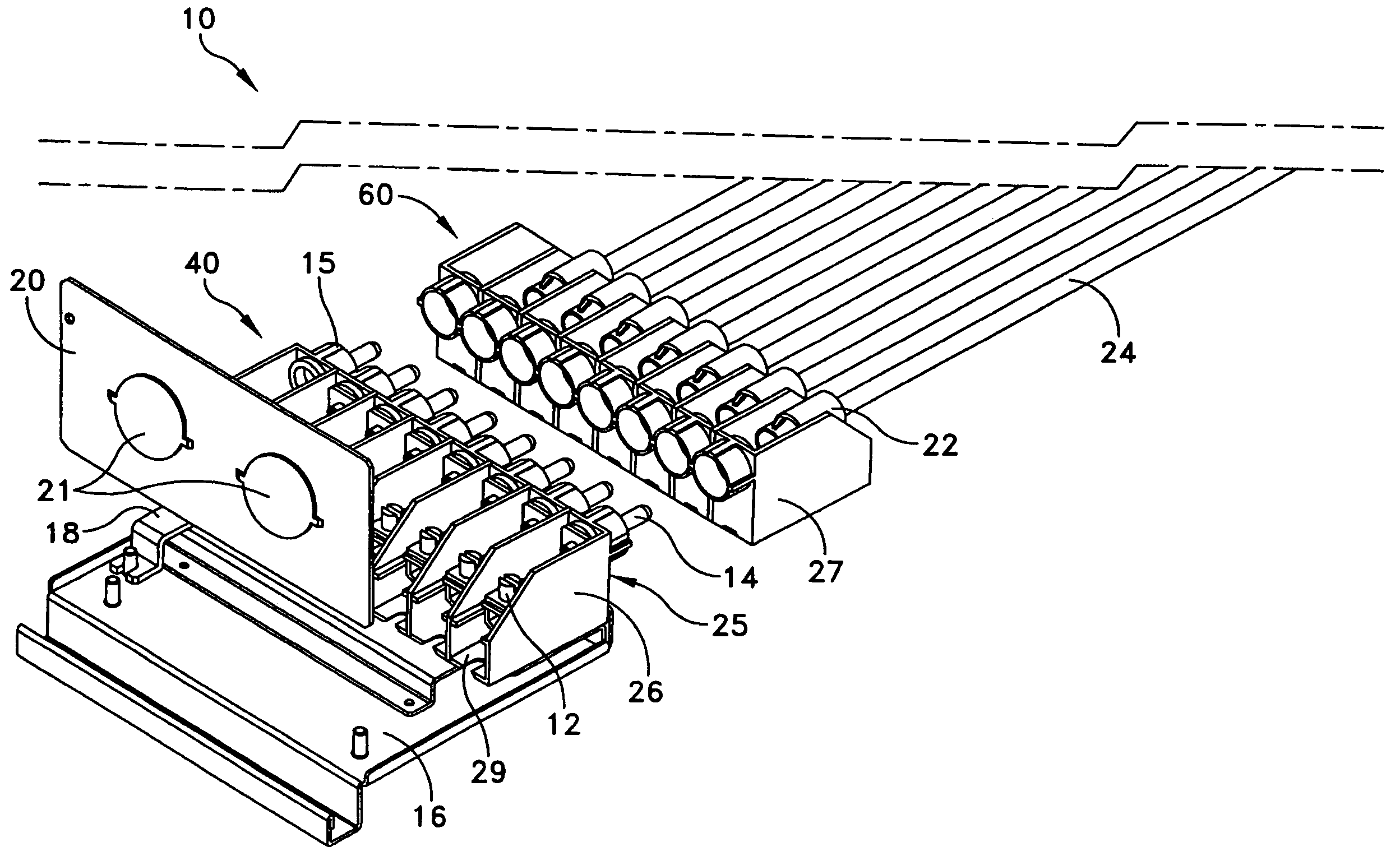
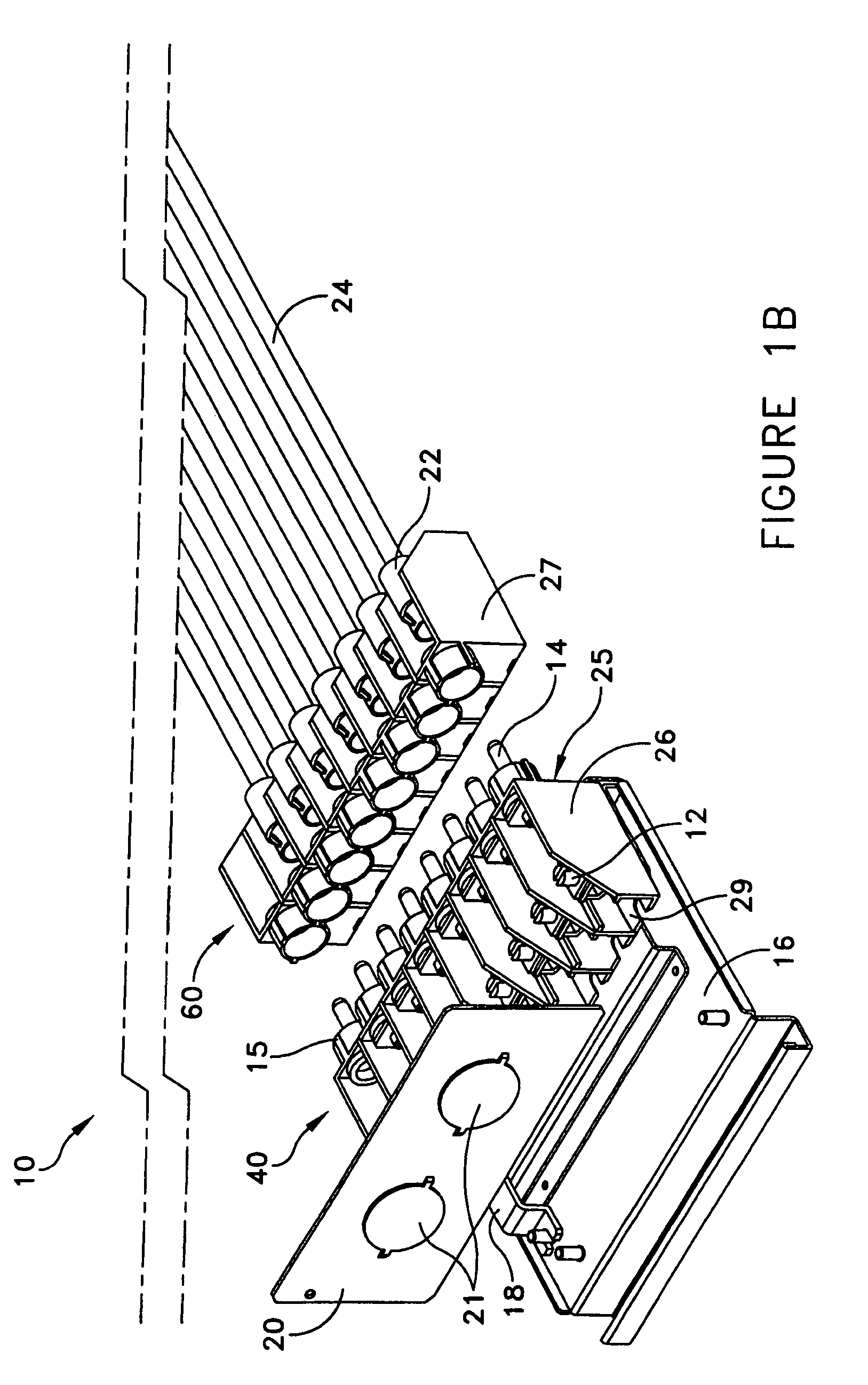
[0016]Embodiments of the invention provide a terminal block input / output connector for use in electrical devices. Embodiments of the invention can be used in uninterruptible power supply systems for electrical connections internally and to external devices. Embodiments of the invention can be used in systems and electronic devices, other than uninterruptible power supplies, that require electrical connections. Still other applications of embodiments of the invention are envisioned.

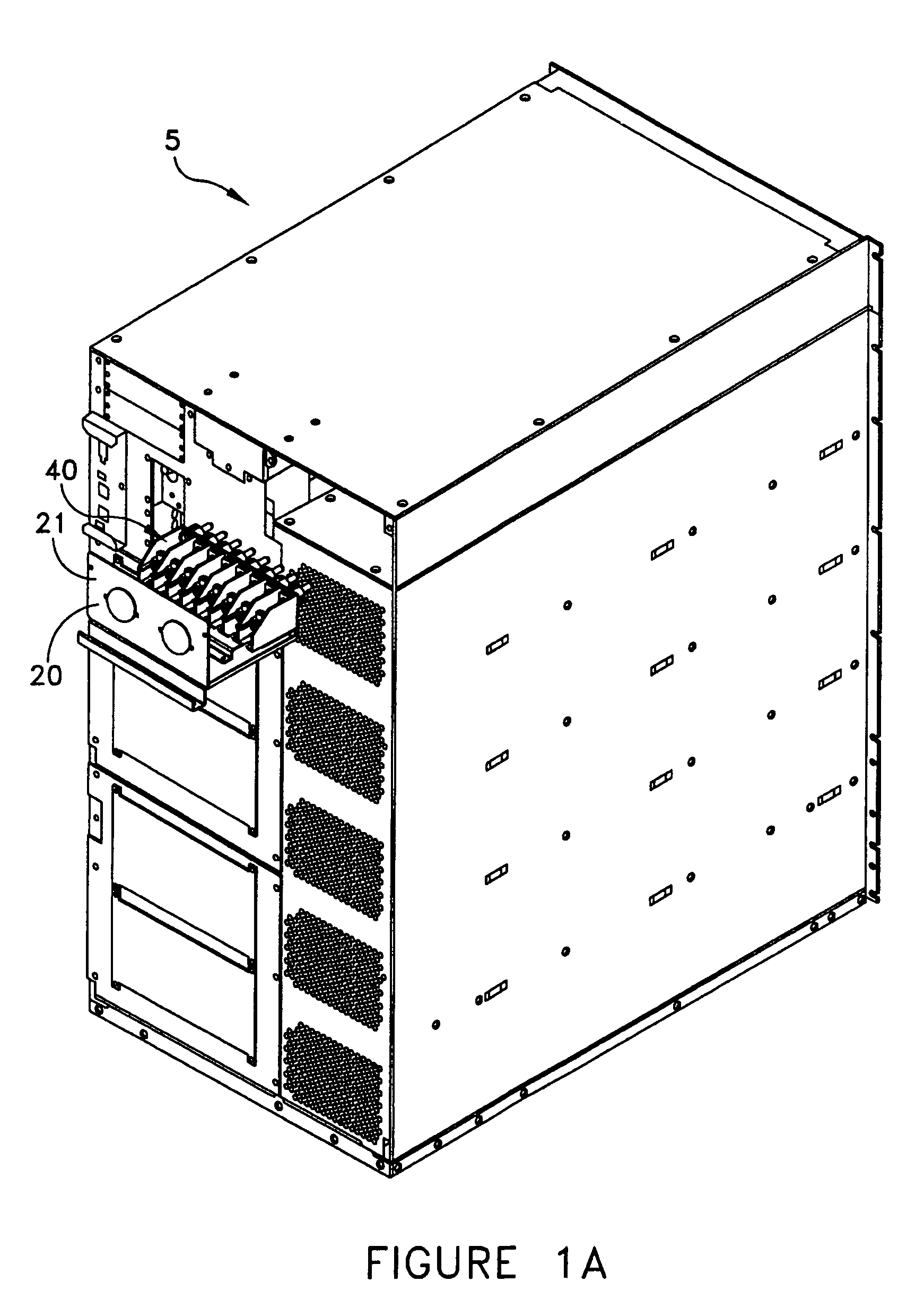
[0017]Referring to FIG. 1A, an uninterruptible power supply (UPS) is shown in a perspective view. The UPS can be a domestic or an international UPS model sold by American Power Conversion Corporation, the assignee of the present invention, such as the APC 16KVA UPS Tower Model, the APC 16KVA UPS Rack-mount model, or the APC 16KVA UPS Tower model with extended run battery, although other models of UPS systems are envisioned, including, but not limited, to additional APC models. A UPS 5 assists in providing ...


PUM

PropertyMeasurementUnit
poweraaaaaaaaaa
flexibleaaaaaaaaaa
sizeaaaaaaaaaa

Abstract

A terminal block for use in an uninterruptible power supply comprises a first portion that includes a plurality of stalls, each of the plurality of stalls having an aperture, and at least one socket positioned in the aperture, the at least one socket arranged to accept a wire from internal portions of the uninterruptible power supply, and a second portion removably connectable to the first portion, the second portion including a plurality of stalls, a plurality of electrical ports, an electrical port positioned in each of the plurality of stalls, and at least one connector pin positioned within one of the plurality of stalls to connect to the at least one socket through the aperture.

Description

FIELD OF THE INVENTION[0001]Embodiments of the present invention are directed to an apparatus for use in electrical installation processes, and more specifically directed to the use of connectors in installing electrical hardware.BACKGROUND OF THE INVENTION[0002]Electronic systems, such as uninterruptible power supplies, generally include terminal blocks to facilitate connection between two groups of wires. It is common to use DIN terminal blocks with screw terminals that are fixed to the electronic system and whereby electrical connections are made. The terminal block is typically connected in a position that is space constrained. In such a space, multiple wire connections can be made, but the connections require manual intervention by a user or an electrician, who must clamp or punch down a wire to achieve connection. In larger systems, less flexible and larger gauge wire is required to complete electrical connections, which increases the difficulty for an electrician in connectin...

Claims


Application Information

Patent Timeline
Patent Type & Authority Patents(United States)
IPC IPC(8): H01R9/22H01R4/36H01R12/24H01R13/631H02J9/00
CPCH01R9/223H01R4/36H01R12/69Y10T29/49147H01R13/6315H02J9/00H01R12/778
Inventor SCHUTTLER, DAVIDSTRANBERG, JOHNFALCINELLI, MICHAELMUTABDZIJA, SRDANBRIGGS, JAMES EDWARD
Owner AMERICA POWER CONVERSION CORP
Why Eureka
Try Eureka