
Vibration-absorbing weight system for golf club head

a golf club head and weight system technology, applied in the field of golf club head vibration-absorbing weight system, can solve the problems of unsatisfactory vibration-absorbing effect, adversely affecting the striking effect, and significantly affecting the overall striking effect, and achieve the effect of simplifying the assembly of the weight member

Inactive Publication Date: 2007-10-16
FUSHENG PRECISION
View PDF17 Cites 53 Cited by
  • Summary
  • Abstract
  • Description
  • Claims
  • Application Information

AI Technical Summary

Benefits of technology

The present invention relates to a golf club head with a vibration-absorbing area behind the striking plate for adjusting the center of gravity. The head includes a gas cushion made of elastomeric material that is filled with gas to provide compressibility. The gas cushion is mounted in a cavity formed by a bladder and is engaged with a weight member. The weight member can be made of metal, plastics, or foaming materials. The gas cushion can have a slit or a coupling section for engagement with the vibration-absorbing area. The rear side of the body can have a back cavity or a compartment below the rear side of the striking plate for receiving the gas cushion and the weight member. The gas cushion can be in direct contact with the rear side of the striking plate or can be in intimate contact with the rear side of the striking plate through the engagement section of the gas cushion. The invention provides a golf club head with improved vibration absorption and weight adjustment.

Problems solved by technology

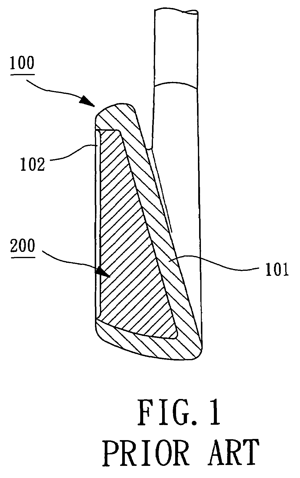
However, since the damping material 200 has a low elastic deforming capability, in the beginning of deformation of the striking face 101, the damping material 200 overpresses against the striking face 101 and thus adversely affects the striking effect.
Thus, the damping material 200 fails to provide the best damping effect, and the overall striking effect is significantly affected.
However, the club head with a weight member has a relatively small damping and provides an unsatisfactory vibration-absorbing effect.
The joint area between the weight member and the club head is liable to crack after a period of time of use, leading to generation of odd sounds and even disengagement of the weight member.

Method used


Image

  • Vibration-absorbing weight system for golf club head
  • Vibration-absorbing weight system for golf club head
  • Vibration-absorbing weight system for golf club head

Examples


first embodiment

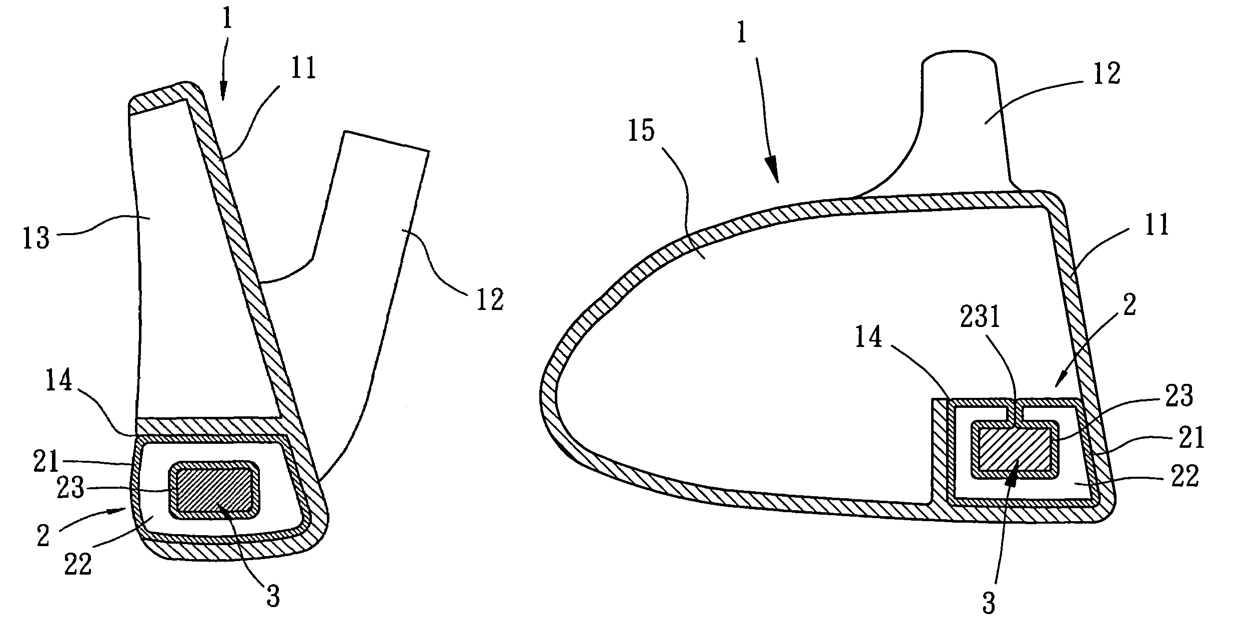
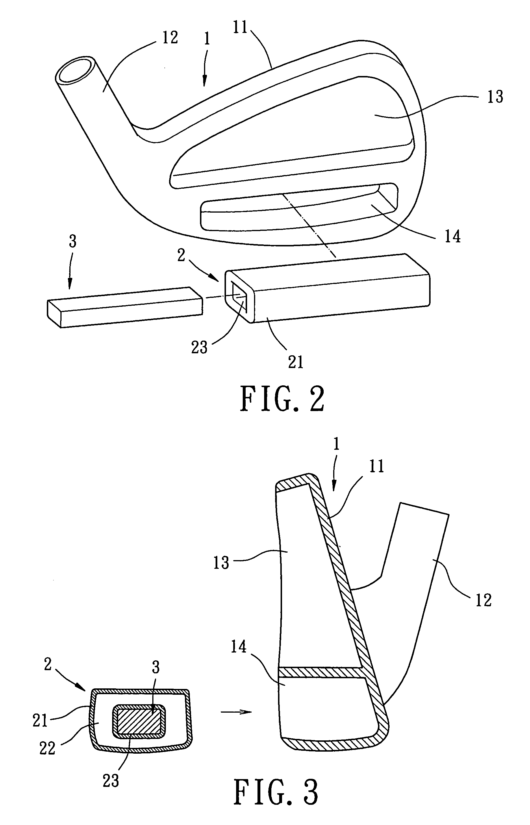
[0039]Referring to FIG. 2 through 4, a golf club head in accordance with the present invention comprises a body 1, at least one gas cushion 2 (only one in this embodiment), and at least one weight member 3 (only one in this embodiment). The body 1 is a body for an iron club head. The body 1 includes a striking plate 11, a hosel 12, a back cavity 13, and a compartment 14 that provides a vibration-absorbing area. The striking plate 11 can be mounted to the body 1 by welding, brazing, insertion, or screwing. The striking plate 11 has a front side for striking golf balls. Alternatively, the body 1 and the striking plate 11 can be integrally formed with each other, with the striking plate 11 providing a striking face of the body 1 for striking golf balls.

[0040]The back cavity 13 is defined in a rear side of the body 1. The rear side of the body 1 is thus exposed to provide a space for rearward deformation of the striking plate 11. The compartment 14 is defined in a bottom or lower portio...

second embodiment

[0050]FIG. 5 illustrates the invention, wherein the body 1 of the golf club head includes two compartments 14a and 14b each for receiving a gas cushion 2 / weight member 3. In the illustrated embodiment, the compartments 14a and 14b are defined in the heel and the toe of the rear side of the body 1 that are respectively adjacent to and proximal to the hosel 12. Since the compartments 14a and 14b are located in an area where the residual vibrations concentrate and since the gas cushions 2 are in intimate contact with the rear side of the striking plate 11, a vibration-absorbing effect is provided while allowing adjustment of the center of gravity as well as improvement (or adjustment) of the inertia moment and the striking effect. Thus, the residual vibrations after striking a golf ball with the golf club head can be effectively absorbed without reducing the momentum. The gripping comfort of the golf club head and the direction controllability and striking accuracy of the golf ball are...

third embodiment

[0051]FIG. 6 illustrates the invention, wherein the body 1 is of wooden club type and includes a striking plate 11, a hosel 12, and at least one compartment 14 (only one in this embodiment). The compartment 14 is defined in a sealed interior space 15 of the body 1 and adjacent to the striking plate 11. At least one gas cushion 2 (only one in this embodiment) and at least one weight member 3 (only one in this embodiment) are mounted in the compartment 14. The gas cushion 2 includes a bladder 21 defining a gas chamber 22 and an engaging section 23. Further, the gas cushion 2 includes a slit 231 through which a receiving space defined by the engaging section 23 is in communication with outside. The weight is inserted into the receiving space defined by the engaging section 23 via the slit 231, and the gas cushion 2 / weight member 3 is then inserted into the compartment 14 of the body 1. The gas cushion 2 / weight member 3 allows adjustment of the center of gravity to improve (or adjust) t...


PUM


Abstract

A golf club head includes a body with a striking plate that has a front side for striking a golf ball and a rear side. A vibration-absorbing area is defined behind the striking plate. At least one gas cushion is mounted in the vibration-absorbing area and includes a bladder defining a gas chamber. The bladder is made of an elastomeric material, and the gas chamber is filled with at least one gas to provide the at least one gas cushion with compressibility. The at least one gas cushion includes an engaging section with which at least one weight member is engaged. The at least one weight member and the at least one gas cushion together adjust a center of gravity of the golf club head while absorbing residual vibrations generated as a result of striking a golf ball.

Description

BACKGROUND OF THE INVENTION[0001]1. Field of the Invention[0002]The present invention relates to a weight system for a golf club head. In particular, the present invention relates to a vibration-absorbing weight system for a golf club head.[0003]2. Description of Related Art[0004]U.S. Pat. No. 5,290,036 discloses a cavity back iron with vibration damping material in the cavity. As illustrated in FIG. 1 of the drawings, the golf club disclosed in U.S. Pat. No. 5,290,036 comprises a head 100 including a striking face 101 and a back cavity 102, which is substantially filled with polyurethane 200 (or damping material). When striking a golf ball with the golf club, the damping material 200 may absorb residual vibrations and thus improve gripping comfort.[0005]To improve striking accuracy and direction controllability of the golf ball, when the golf ball begins to contact with the striking face 101, the striking face 101 should be rapidly and significantly compressed when subjected to a s...

Claims


Application Information

Patent Timeline
Patent Type & Authority Patents(United States)
IPC IPC(8): A63B53/04
CPCA63B53/0466A63B53/047A63B53/0475A63B2053/0491A63B59/0092A63B60/54A63B60/02
Inventor HOU, WEN-CHING
Owner FUSHENG PRECISION
Learn More