Black fringe wavefront sensor

a wavefront sensor and black fringe technology, applied in the field of closed loop correction of phase aberrations using black fringe wavefront sensors, can solve the problems of mass reconstructors and sensor is not highly scalabl

Active Publication Date: 2007-10-16
LOCKHEED MARTIN CORP
View PDF8 Cites 20 Cited by
  • Summary
  • Abstract
  • Description
  • Claims
  • Application Information

AI Technical Summary

Problems solved by technology

To its disadvantage, however, conventional Shack-Hartmann AO sensor 112

Method used


Image

  • Black fringe wavefront sensor
  • Black fringe wavefront sensor
  • Black fringe wavefront sensor

Examples


Embodiment Construction

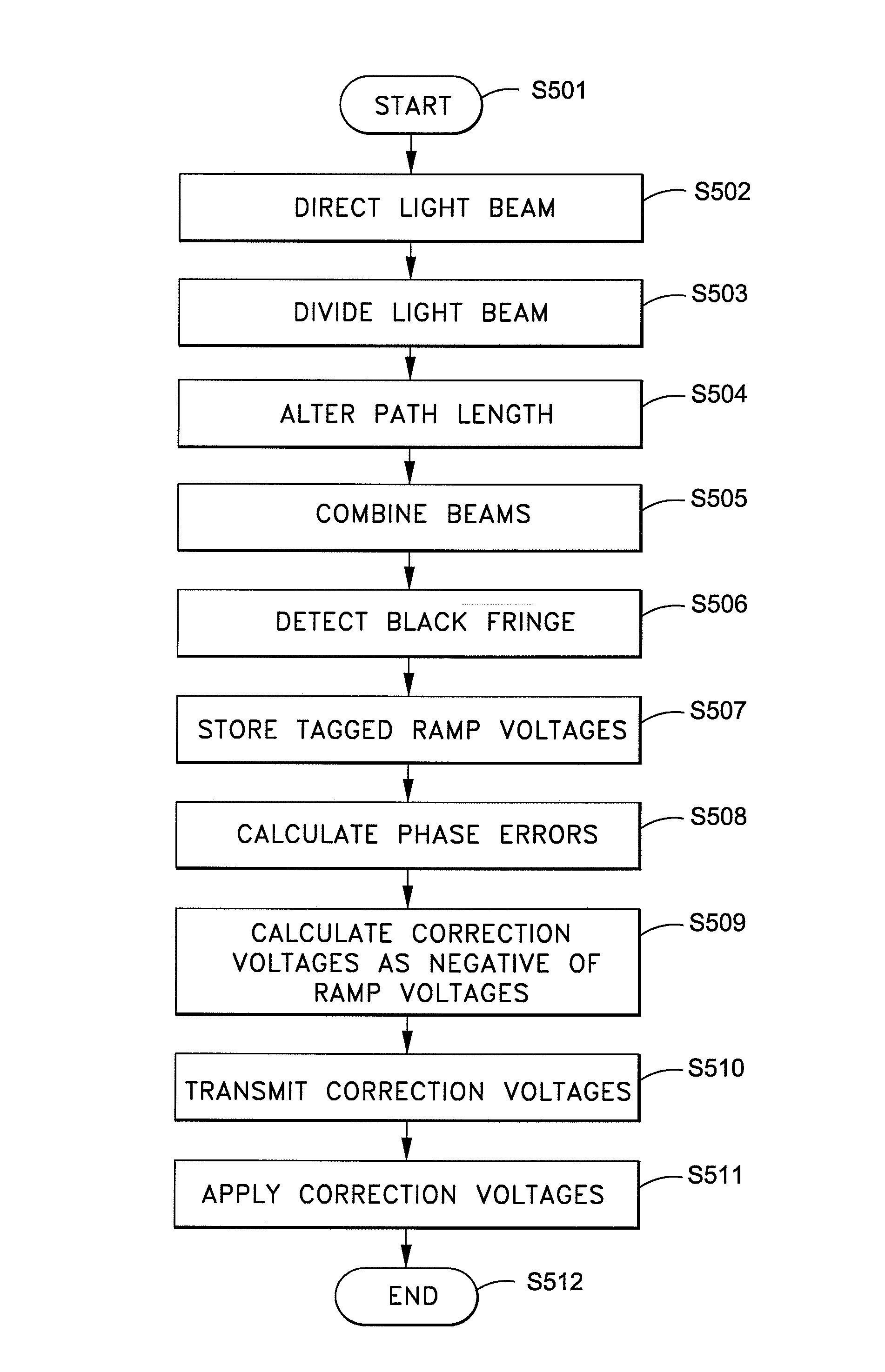
[0020]The present invention provides for the closed loop correction of phase aberrations using a black fringe wavefront sensor, to avoid the use of a reconstructor.

[0021]FIG. 3 depicts a system for performing closed loop correction of phase aberrations according to one example embodiment of the present invention. Briefly, the system includes an adaptive optical device and a black fringe wavefront sensor. The black fringe wavefront sensor further includes a plurality of optical elements, the plurality of optical elements dividing an incoming light beam into a measurement beam and a reference beam, and combining the measurement beam and the reference beam into a common output beam. The plurality of optical elements includes a test mirror. The black fringe wavefront sensor further includes a modulator affixed to the test mirror, the modulator modulating based upon a ramp voltage, thereby altering optical path length of the measurement beam and location of black fringe, and a plurality ...


PUM


Abstract

A method of performing closed loop correction of phase aberrations, including the steps of directing an incoming light beam into a black fringe wavefront sensor via an adaptive optical device (“AOD”), dividing the incoming light beam into measurement and reference beams, altering the path length of the measurement beam and the location of the black fringe by modulating a ramp voltage of a modulator, combining the measurement and reference beams into a common output beam, detecting the black fringe in the common output beam using detectors mapped to the AOD, storing, as tagged ramp voltages, a corresponding ramp voltage for each detector when it detects black fringe, calculating phase errors based upon the tagged ramp voltages and modulator scaling, calculating adaptive optics correction voltages based upon the phase errors, transmitting and applying the correction voltages to the AOD to correct phase aberrations of the incoming light beam via phase conjugation.

Description

STATEMENT REGARDING FEDERALLY SPONSORED RESEARCH OR DEVELOPMENT[0001]Not applicable.FIELD OF THE INVENTION[0002]The present invention generally relates to wavefront sensors and, in particular, relates to the closed loop correction of phase aberrations using a black fringe wavefront sensor.BACKGROUND OF THE INVENTION[0003]There exists a need for adaptive optics systems which can correct for light distortions which occur in the medium of transmission. Conventional adaptive optics (“AO”) systems measure the characteristics of a lens, and correct for distortions using a computer-controlled deformable mirror, where the device which measures the distortions in the incoming wavefront of light is known as a wavefront sensor.[0004]FIG. 1 depicts conventional AO system 100, which is an example of a closed loop AO system commonly used in the astronomical community. Light beam 101 emanating from nominal point source 102, a star, is directed through reflective and refractive elements within tele...

Claims


Application Information

Patent Timeline
IPC IPC(8): G01B9/02
CPCG01J9/02
Inventor TANSEY, RICHARD J.
Owner LOCKHEED MARTIN CORP
Why Eureka
Try Eureka