Image forming apparatus and power control method

a technology of image forming apparatus and power control method, which is applied in the direction of digital output to print units, liquid/fluent solid measurement, instruments, etc., can solve the problems of power saving effect that cannot be expected, foregoing conventional technique, etc., and achieves the effect of power saving more effectiv

Inactive Publication Date: 2007-10-16
CANON KK
View PDF9 Cites 18 Cited by
  • Summary
  • Abstract
  • Description
  • Claims
  • Application Information

AI Technical Summary

Benefits of technology

[0013]The invention is made to solve the above problems and it is an object of the invention to provide a mechanism which can realize power saving more effective than the conventional one and can make a response of an updated status to a status request from an external apparatus without making the user be aware or execute any tiresome operations.

Problems solved by technology

The foregoing conventional technique, however, has the following problems.
Such a situation is contradictory to a recent energy saving purpose.
However, it is presumed that under conditions such that a plurality of users share the printer, the status requests are frequently made by the plurality of users, so that a power saving effect cannot be expected.

Method used


Image

  • Image forming apparatus and power control method
  • Image forming apparatus and power control method
  • Image forming apparatus and power control method

Examples


first embodiment

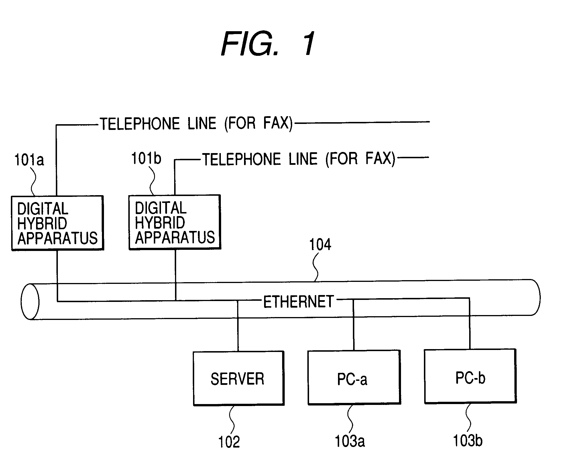
[0033]FIG. 1 is a block diagram showing an example of a network system to which an image forming apparatus showing the first embodiment of the invention can be applied. Naturally, image forming apparatuses to which the invention can be applied include: a printing apparatus (printer) and a facsimile apparatus using an electrophotographic system or an ink jet system or a digital hybrid apparatus for executing compound image processes including a printing process and a facsimile process. The digital hybrid apparatus will be described as an example hereinbelow.

[0034]In FIG. 1, reference numerals 101a and 101b denote the digital hybrid apparatuses. As will be explained hereinlater, an electric power is supplied from the power source 203 to the printer unit 231, reader unit 226, and controller unit 232, so that those digital hybrid apparatuses operate.

[0035]Reference numeral 102 denotes the server and 103a and 103b indicate the PCs (personal computers) and those apparatuses are connected ...

second embodiment

[0196]The first embodiment has been described on the assumption that the sub-CPU (1-chip microcomputer Q702) and the main chip Q701 are physically separately provided as shown in FIG. 7. However, the invention is not limited to it but there is also presumed a case where a mode for making a predetermined chip (CPU) operative by a high frequency clock and a mode for making it operative by a low frequency clock are made to correspond to the main chip and the sub-chip, respectively, or a case where a local power source in the predetermined chip is saved and the mode for making the chip operative by small electric power consumption is made to correspond to the sub-chip.

[0197]A construction of data processing programs which can be read out by the image forming apparatus according to the invention will be described hereinbelow with reference to a memory map shown in FIG. 15.

[0198]FIG. 15 is a diagram for explaining the memory map in a memory medium for storing various data processing progr...


PUM


Abstract

A sub-CPU copes with a status obtaining request from a network in a sleep mode. Further, necessary least power control for updating a status in an image forming apparatus in the sleep mode is realized by the sub-CPU.

Description

BACKGROUND OF THE INVENTION[0001]1. Field of the Invention[0002]The invention relates to an image forming apparatus which is connected to a network via network connecting means and can execute a predetermined job process and to a power control method.[0003]2. Related Background Art[0004]Hitherto, a system constructed by connecting printers (including a copying apparatus and a hybrid apparatus) and computers via a network exists.[0005]FIG. 16 is a block diagram showing an example of a conventional network system including an image forming apparatus and corresponds to, for example, a construction of a network system which is used by a plurality of users in a network environment.[0006]In FIG. 16, the network system is constructed by connecting a plurality of PCs (personal computers) 103a and 103b, a plurality of copying apparatuses 101a and 101b, and a server 102 via a network. The copying apparatus (each of the copying apparatuses 101a and 101b) is constructed by a printer unit 231, a...

Claims


Application Information

Patent Timeline
Patent Type & Authority Patents(United States)
IPC IPC(8): B41F33/00B41J29/38G03G21/00G06K15/00H04N1/00
CPCG06K15/00G06K2215/0017G03G21/00
Inventor TAKEDA, TOMOYUKIMIYAMOTO, KAZUKIMIURA, SHIGEOUCHIZONO, TAKEHARUUSHIRO, TAKAHIROTAKATA, SHINICHI
Owner CANON KK
Why Eureka
Try Eureka