
Detachable developing apparatus and driving apparatus of the same

a technology of developing apparatus and driving apparatus, which is applied in the direction of electrographic process apparatus, instruments, gearing, etc., can solve the problems of unstable development nips, inability to form images, and eccentricity, so as to reduce load and minimize friction

Active Publication Date: 2007-10-16
HEWLETT PACKARD DEV CO LP
View PDF19 Cites 13 Cited by
  • Summary
  • Abstract
  • Description
  • Claims
  • Application Information

AI Technical Summary

Benefits of technology

[0013]Accordingly, it is an aspect of the present invention to minimize friction occurring at sliding slots of a coupling disc by reducing a load applied to a coupling member or a driving gear which transfers driving power to a developing unit.
[0014]It is also an aspect of the present invention to maintain a nip depth between a photosensitive drum and a developing roller and enhance quality of a printed image by minimizing friction occurring at the sliding slots of the coupling disc and thereby causing the principal function of an Oldham's coupling, i.e., the function of correcting eccentricity occurring at a connected shaft to function smoothly.
[0015]It is also an aspect of the present invention to reduce cost by simplifying the structure of a coupling member.
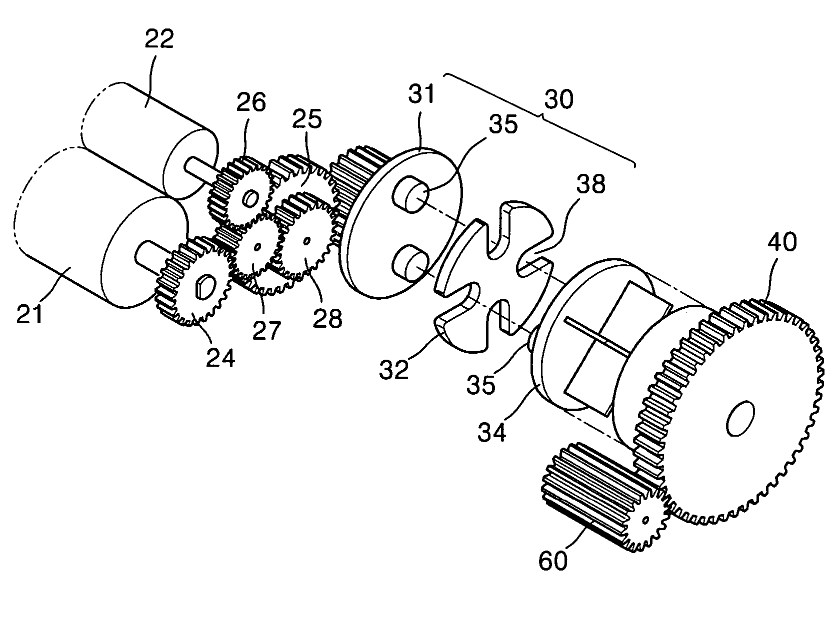
[0019]Furthermore, the foregoing and / or other aspects are achieved by providing a driving apparatus of a developing apparatus to transfer a driving power of a driving element of the developing apparatus to a developing element of the developing apparatus including a shaft, including: a coupling member which is connected to the driving element and to which the driving power is transferred from the driving element, and correcting an eccentricity of the shaft between the driving element and the coupling member; and a power transferring portion including a plurality of gears so as to transfer the driving power from the coupling member to the developing element, wherein at least one of the plurality of gears is a reduction gear to reduce a load applied to the coupling member from the developing element.

Problems solved by technology

However, when the photosensitive unit and the developing unit are combined in one cartridge as above-mentioned, there is a problem in which even though the usable life of the photosensitive unit is generally much longer than that of the developing unit, the photosensitive unit must be replaced together with the developing unit when the developing unit reaches the end of its usable life, even if the photosensitive unit operates normally.
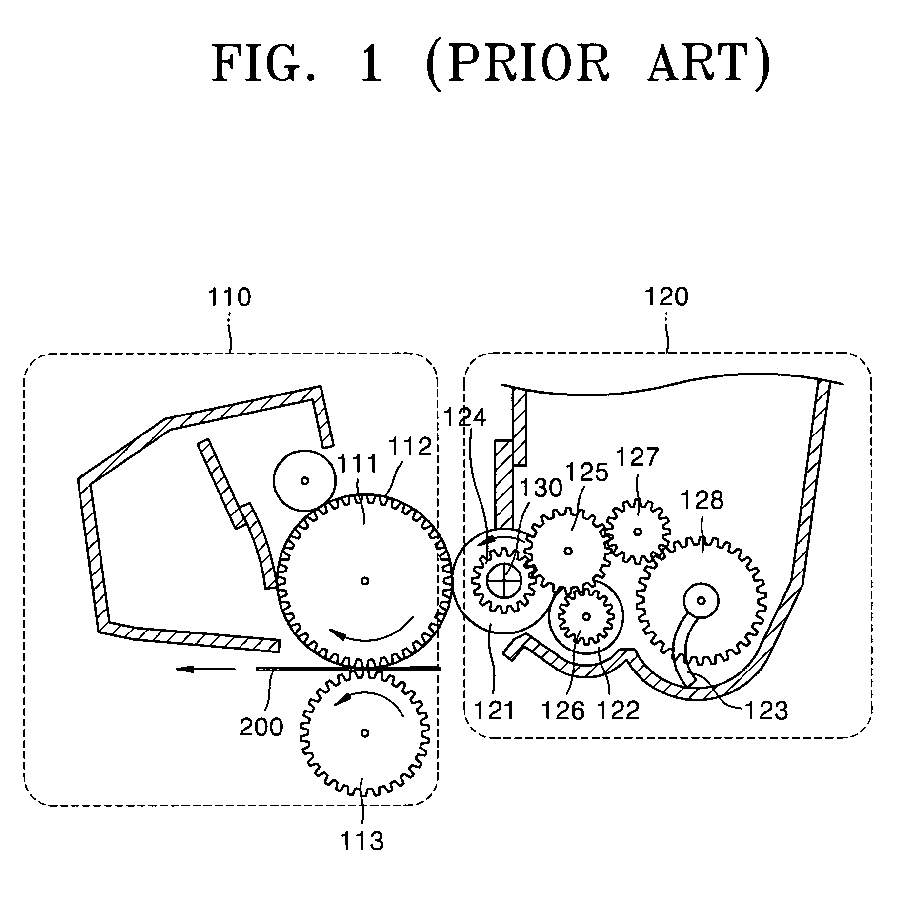
However, at least some eccentricity will occur due to tolerance or the like occurring during manufacturing and assembling processes.
The nip depth between the photosensitive drum 111 and the developing roller 121 is thus uneven, resulting in unstable development nips.
When the development nip depth is smaller than the range values, the development nip is not formed, and therefore image formation is not possible.
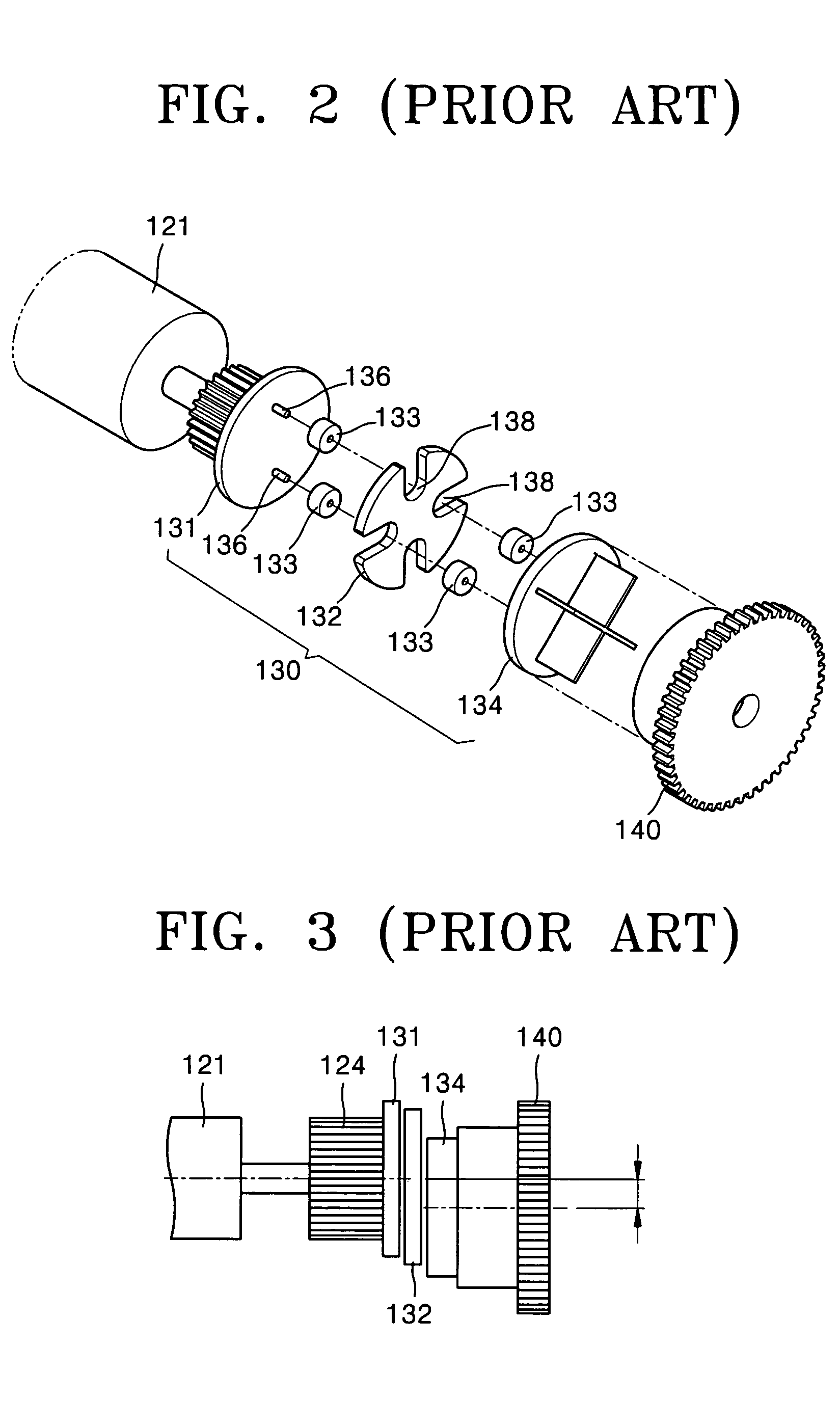
Consequently, the structure of the coupling member becomes very complex due to the installation of such sliding rollers 133, and the cost thereof increases due to the installation of the rotation shafts 136 and the sliding rollers 133.

Method used


Image

  • Detachable developing apparatus and driving apparatus of the same
  • Detachable developing apparatus and driving apparatus of the same
  • Detachable developing apparatus and driving apparatus of the same

Examples


Embodiment Construction

[0028]Reference will now be made in detail to the embodiment of the present invention, an example of which is illustrated in the accompanying drawings, wherein like reference numerals refer to the like elements throughout. The embodiment is described below to explain the present invention by referring to the figures.

[0029]FIG. 5 schematically shows a detachable developing apparatus according to an embodiment of the present invention. A photosensitive unit 10 and a developing unit 20 are separately installed at a main body of a printer, copier or the like, and are separately driven by separate driving gears. In addition, in a state in which the photosensitive unit 10 is fixed to the main body, a photosensitive drum 11 of the photosensitive unit 10 and a developing roller 21 of the developing unit 20 come into contact with each other by pressing the developing unit 20 toward the photosensitive unit 10 with a force of a spring or the like. When driving power is transferred from a photo...


PUM


Abstract

A driving apparatus of a detachable developing apparatus, and the detachable developing apparatus using the driving apparatus. The driving apparatus includes: a coupling member including a coupling drive which is connected to a driving element and to which driving power is transferred from the driving element, a coupling gear to which driving power is transferred from the coupling drive, and a coupling disc positioned between the coupling drive and the coupling gear for flexibly connecting the coupling drive and the coupling gear; and a power transferring portion including a plurality of gears to transfer driving power from the coupling member to the developing element and the toner supply element. At least one of the plurality of gears is a reduction gear for reducing a load applied to the coupling member from the developing element and the toner supply element.

Description

CROSS-REFERENCE TO RELATED APPLICATIONS[0001]This application claims the benefit of Korean Patent Application No. 2004-6972, filed on Feb. 3, 2004, in the Korean Intellectual Property Office, the disclosure of which is incorporated herein in its entirety by reference.BACKGROUND OF THE INVENTION[0002]1. Field of the Invention[0003]The present invention relates to a driving apparatus of a developing apparatus of a laser printer, copier, or the like, and a developing apparatus using the driving apparatus, and more particularly, to a driving apparatus of a detachable developing apparatus capable of enhancing quality of a printed image by inducing uniform rotation and dampening of vibration even when a photosensitive unit and a developing unit are separately driven, and the detachable developing apparatus using the driving apparatus.[0004]2. Description of the Related Art[0005]In a laser printer, copier, combined printer, or the like, a developing apparatus for printing a processed image...

Claims


Application Information

Patent Timeline
Patent Type & Authority Patents(United States)
IPC IPC(8): G03G15/00F16H1/20G03G15/08F16H1/26G03G15/06G03G21/00G03G21/16
CPCG03G15/757G03G2215/06G03G15/06
Inventor NOH, JOO-HWAN
Owner HEWLETT PACKARD DEV CO LP
Learn More