Fluid level measurement device

a technology of fluid level and measurement device, which is applied in the direction of volume metering, machines/engines, instruments, etc., can solve the problems of inattention, sloppiness, and inefficiency of measurement personal, and achieves the effects of simple design and construction, easy installation and calibration, and low cos

Inactive Publication Date: 2007-10-23
THOMPSON DOUGLAS A
View PDF8 Cites 11 Cited by
  • Summary
  • Abstract
  • Description
  • Claims
  • Application Information

AI Technical Summary

Benefits of technology

[0007]The fluid level measurement device of the present invention addresses the aforementioned needs in the art. The fluid level measurement device measures the high level mark and the low level mark within a fluid body such as an ocean. Once the fluid level measurement device is properly installed, it requires no further technician involvement until

Problems solved by technology

The problem with this method is that there is a substantial amount of time between high tide and low tide resulting in an underutilization of human capital.
Additionally, many tidal measurements are performed across multiple tidal cycles which adds to the capital inefficiency and also leads to inattention and sloppiness by the measurement personal.
The problems with such devices is that they are extremely expensive and tend to be difficult to calibrate and operate

Method used


Image

  • Fluid level measurement device
  • Fluid level measurement device
  • Fluid level measurement device

Examples


Embodiment Construction

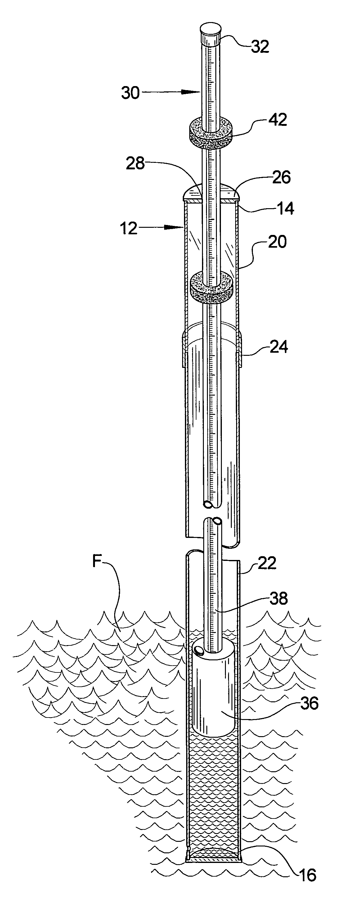
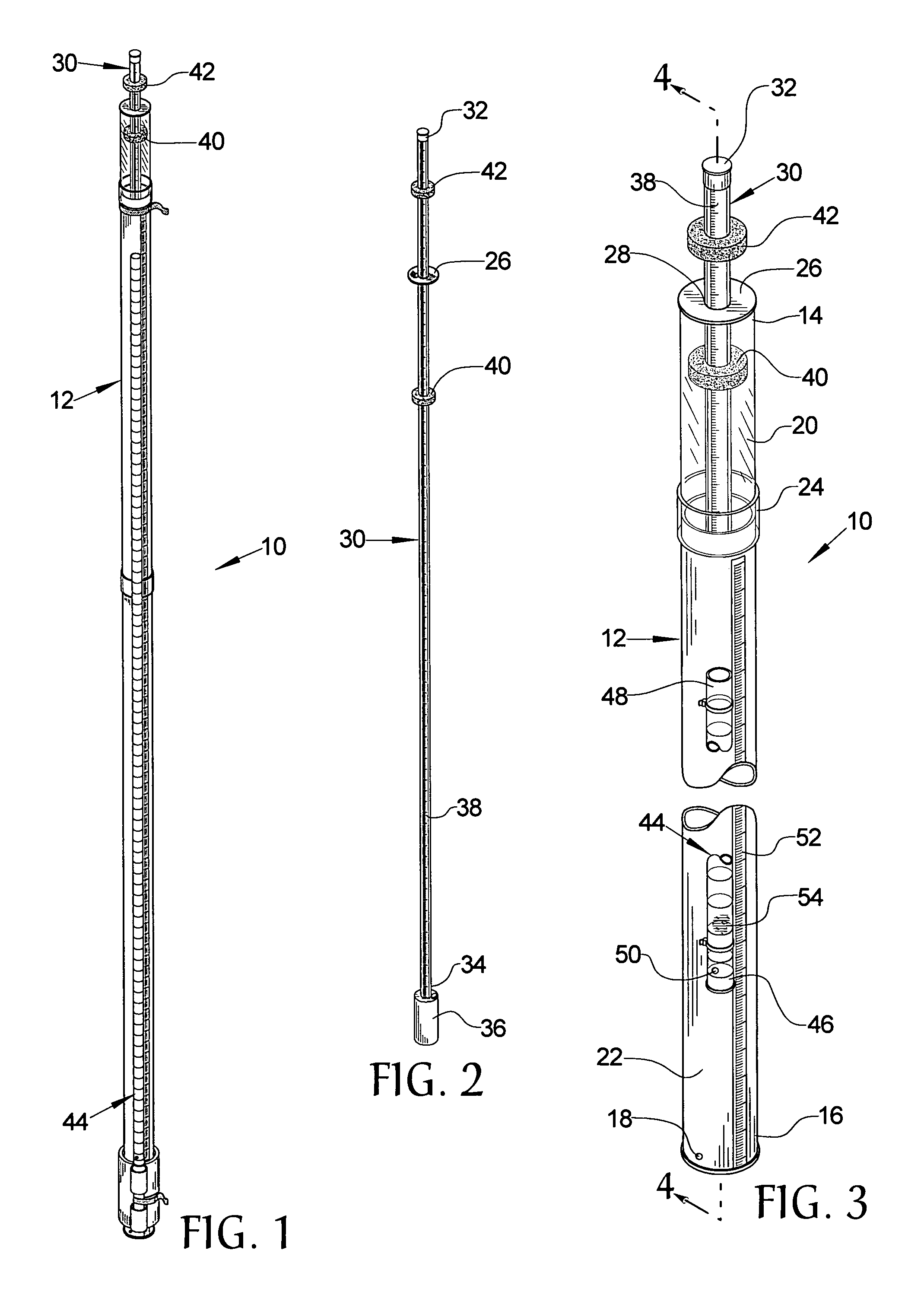
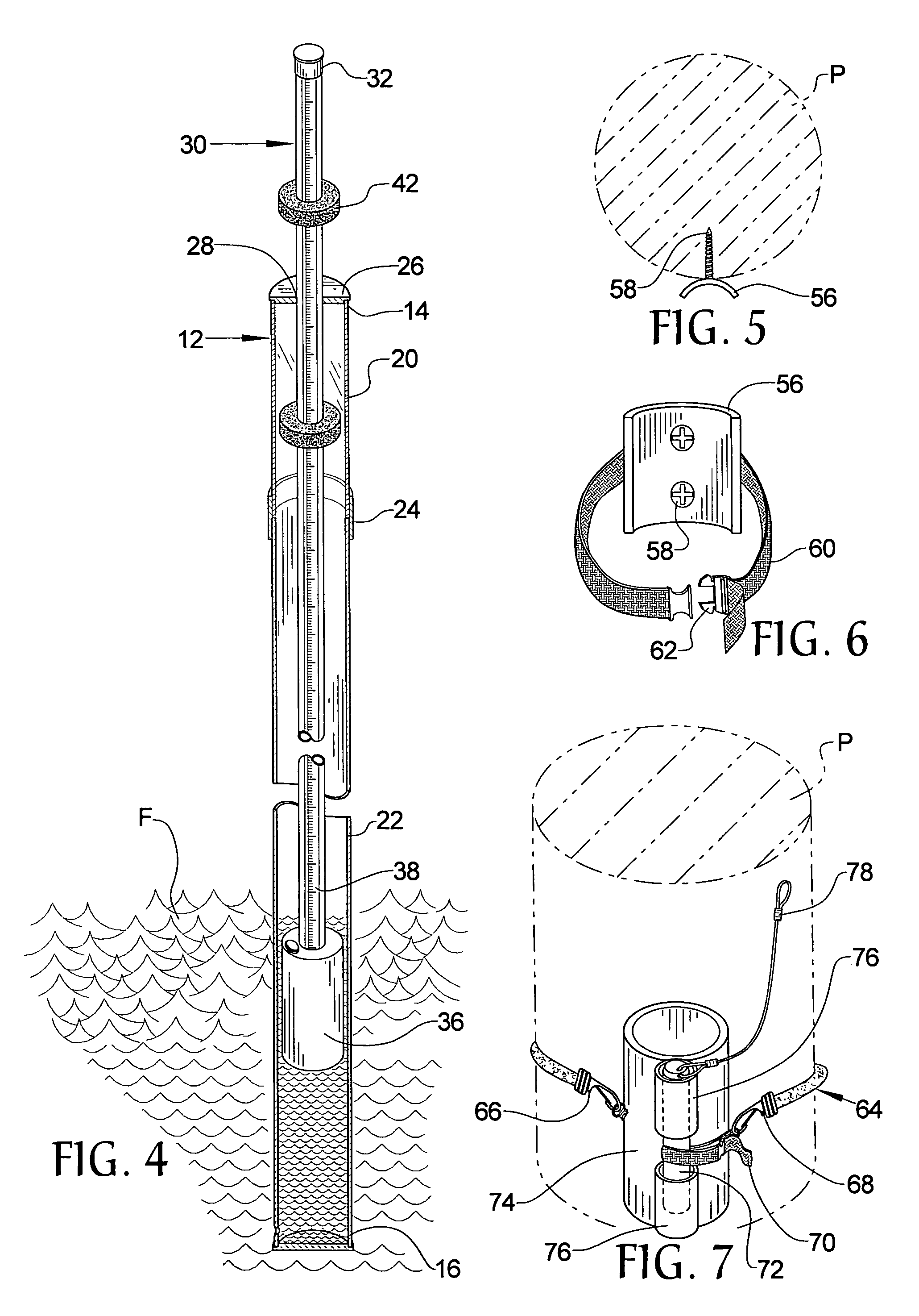
[0017]Referring now to the drawings, it is seen that the fluid level measurement device of the present invention, generally denoted by reference numeral 10, is comprised of a hollow tubular housing 12 having a top end 14 and a bottom end 16, which may be capped, with an opening 18 located proximate the bottom end 16 for allowing fluid F to enter and leave the interior of the housing 12. The housing 12 may be of monolithic construction, or, as illustrated, may be made of two or more sections, such as an upper section 20 and a lower section 22 joined together by a collar 24, which may frictionally hold each section 20 and 22. By utilizing a multi-sectional design, service access to the interior of the housing 12 is easy to achieve and the upper section 20 may be made from a transparent material in order to allow visual access into the interior so as to be able to take quick measurements as more fully discussed below. A cap 26 has an opening 28 and is attached, removably or otherwise, ...


PUM


Abstract

A device measures the high and low fluid levels of a fluid body. A housing has a shaft with a buoyant weight, the shaft protruding through a cap on the housing's top and capable of sliding through the cap. A first ring encompasses the shaft and is initially positioned immediately below the cap, while a second ring is positioned immediately above the cap. As fluid enters the housing, the shaft rises in lockstep with the fluid level causing the first ring to be pushed downwardly on the shaft and when the fluid level falls, the shaft falls causing the second ring to be pushed upwardly along the shaft. The distance between the rings is the amount of fluid level variation. A debris tube attached to the housing measures the upper limit of fluid level. Subtracting the amount of variation from this upper limit yields the lower fluid level limit.

Description

BACKGROUND OF THE INVENTION[0001]1. Field of the Invention[0002]The present invention relates to a fluid level measurement device that can easily and accurately measure both the high fluid level and the low fluid level for a body of fluid over a period of time.[0003]2. Background of the Prior Art[0004]The levels of most of the earth's navigable bodies of water are not constant but fluctuate between a low level or a low tide and a high level or a high tide. The variations in the levels are generated partly by the unhomogeneous gravitational fields of the moon, the Sun, and the planets of the solar system and partly by the deformation of the Earth. A second component that acts on tides are the gravitational effects of the water masses in oceans and seas moved by these water forces and the deformations of the Earth-due to weight of the water masses. As the tide levels are critical to a variety of interests, including navigation, boundaries, environmental assessments, and sea level chan...

Claims


Application Information

Patent Timeline
IPC IPC(8): G01C13/00G01F23/30
CPCG01C13/004G01F23/58G01F23/56G01F23/303
Inventor THOMPSON, DOUGLAS A.
Owner THOMPSON DOUGLAS A
Why Eureka
Try Eureka