Supercharge Your Innovation With Domain-Expert AI Agents!

Oil drain plug wrench

a technology of oil drain plugs and wrenches, which is applied in the direction of wrenches, screwdrivers, manufacturing tools, etc., can solve the problems of slow open end and fixed box end wrenches, difficult to remove, and each tool is problematic, so as to achieve the effect of easy removal or installation

Inactive Publication Date: 2007-10-23
APEX BRANDS
View PDF30 Cites 6 Cited by
  • Summary
  • Abstract
  • Description
  • Claims
  • Application Information

AI Technical Summary

Benefits of technology

The present invention is an oil drain plug wrench that allows for easy removal or installation of oil drain plugs. The wrench has a handle, head, and a cylindrical rotor with teeth that engage with a tooth on the inner surface of the wrench head. The rotor has two parts, and the second part has a larger radius and a cavity that engages the tooth on the inner surface of the wrench head. The wrench can be rotated in opposite directions to ratchet over the tooth on the inner surface of the wrench head. The technical effects of this invention include improved grip, durability, and ease of use for removing and installing oil drain plugs.

Problems solved by technology

Since the oil is hot, the oil plug is can be hot to the touch, making it difficult to remove.
However, each tool is problematic.
For example, open ends and fixed box end wrenches are slow because of the need to mount and dismount the wrench on the oil drain plug each time the wrench is indexed.
Ratcheting wrenches are problematic because once the oil drain plug is broken loose, there is not enough friction between the threads of the oil drain pan and the oil plug to allow the wrench to ratchet.

Method used


Image

  • Oil drain plug wrench
  • Oil drain plug wrench
  • Oil drain plug wrench

Examples


Embodiment Construction

[0024]Reference will now be made in detail to presently preferred embodiments of the invention, one or more examples of which are illustrated in the accompanying drawings. Each example is provided by way of explanation of the invention, not limitation of the invention. In fact, it will be apparent to those skilled in the art that modifications and variations can be made in the present invention without departing from the scope and spirit thereof. For instance, features illustrated or described as part of one embodiment may be used on another embodiment to yield a still further embodiment. Thus, it is intended that the present invention covers such modifications and variations as come within the scope of the appended claims and their equivalents.

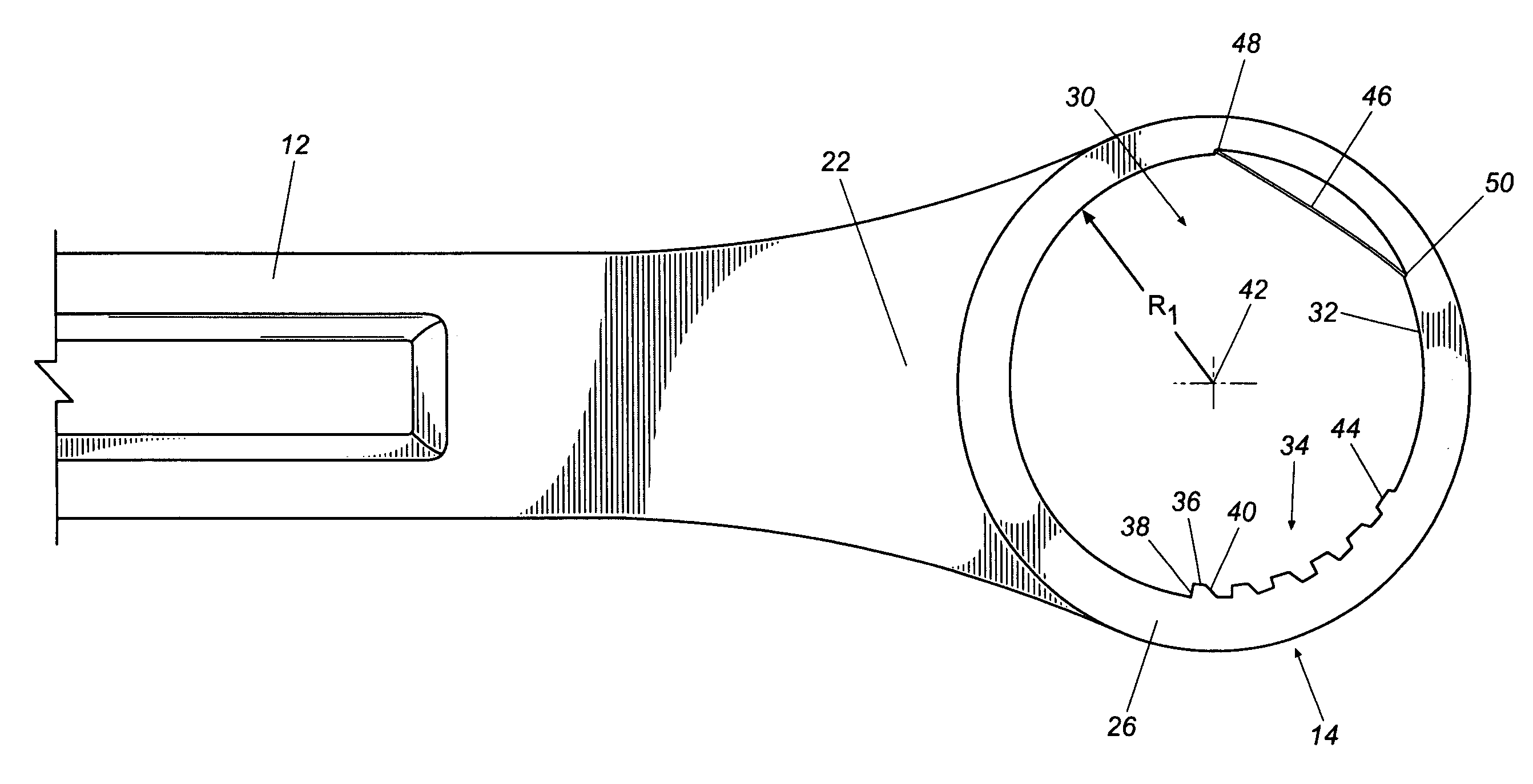
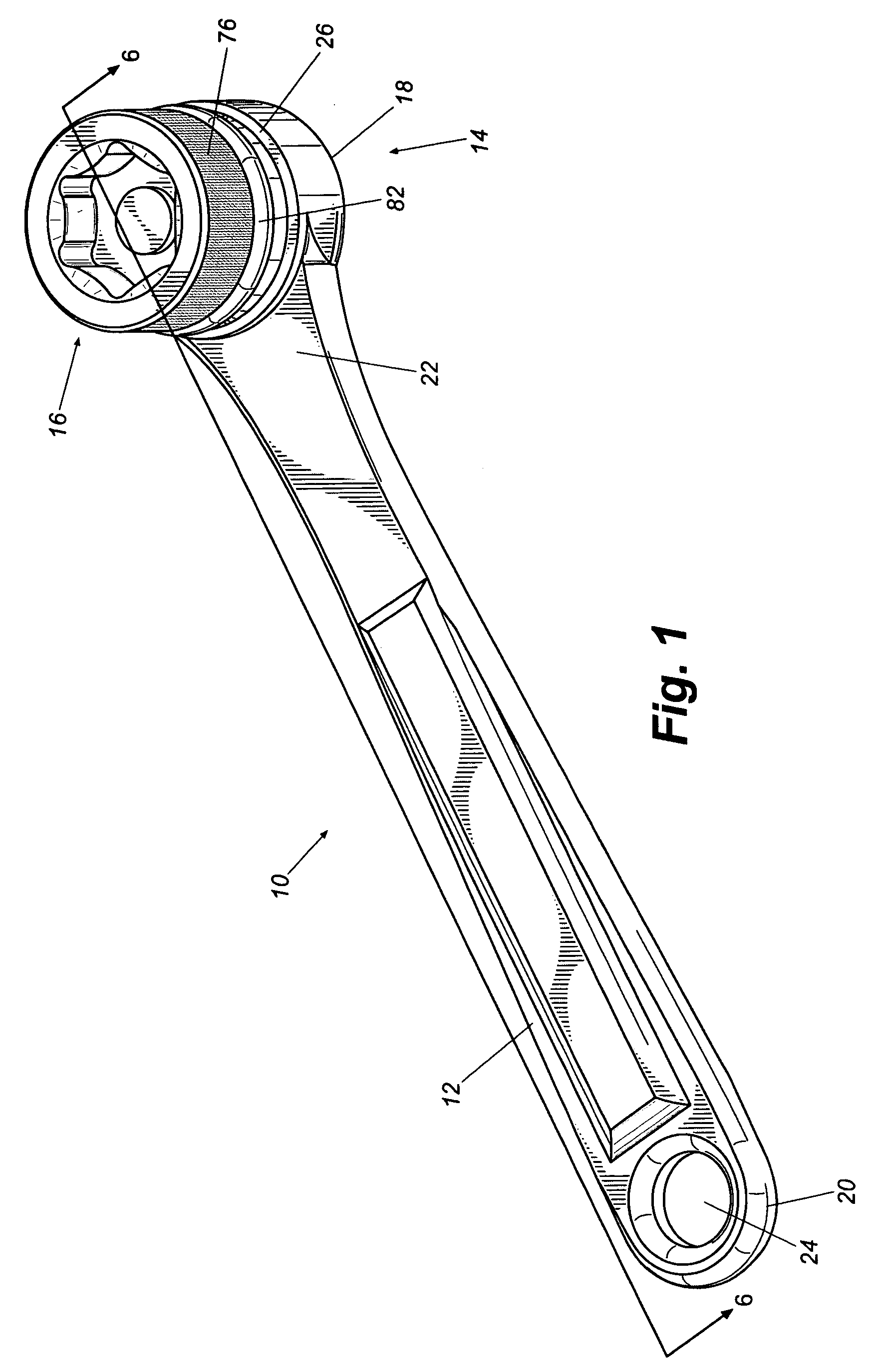
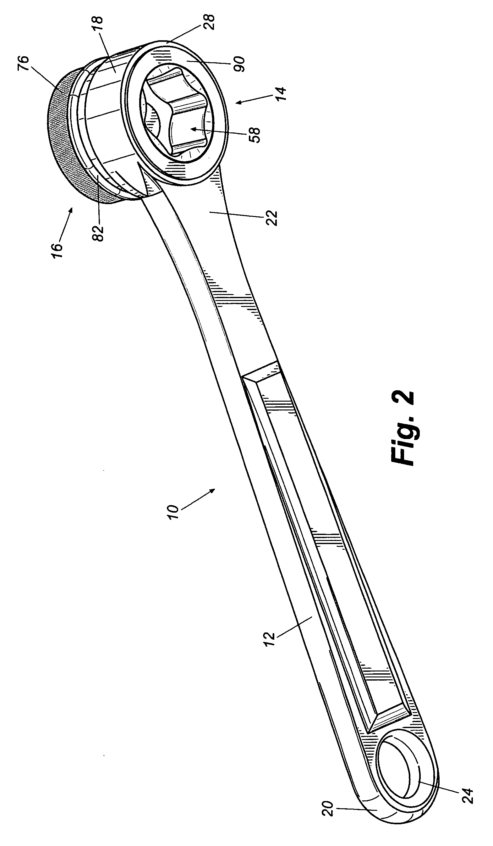
[0025]Referring to the drawings, and particularly to FIGS. 1, 2 and 3, a wrench 10 has a body with a handle 12, a head 14 and a rotor 16. The body and rotor may be formed from any suitable material, for example one or a combination of steel, ...


PUM


Abstract

An oil drain plug wrench is provided to enable a user to more easily remove and install an oil drain plug. The wrench includes a rotor with two cavities on opposite sides of a rotor. When either of the cavities engages a workpiece, the wrench is capable of applying torque to the workpiece in a first rotational direction and ratcheting in a second rotational direction. A flange is provided on the outer diameter of the rotor to allow a user to remove or install an oil drain plug by hand.

Description

BACKGROUND OF THE INVENTION[0001]The present invention relates generally to ratcheting tools, and more particularly to a ratchet wrench that allows a user to easily remove an oil drain plug.[0002]Changing the oil in a motorized vehicle requires removal of the oil drain plug so old oil can drain from the oil pan into a collection tank. In the case of businesses that specialize in fast oil change service, the oil is drained from the engine while it is still hot so that contaminants and impurities are carried out with the hot oil before having a chance to settle and cling to the bottom of the oil pan as the oil cools. Since the oil is hot, the oil plug is can be hot to the touch, making it difficult to remove. Once the oil is drained, the oil drain plug is replaced and new oil is added to the engine through an oil fill port.[0003]Previously, the oil drain plug was removed using a variety of tools, such as an open end wrench, a fixed box end wrench, pliers, a ratcheting socket wrench or...

Claims


Application Information

Patent Timeline
Patent Type & Authority Patents(United States)
IPC IPC(8): B25B13/46B25B13/00
CPCB25B13/06B25B13/463B25B27/0042B25B23/12B25B13/48
Inventor CHACONAS, PETER C.
Owner APEX BRANDS
Features
  • R&D
  • Intellectual Property
  • Life Sciences
  • Materials
  • Tech Scout
  • Unparalleled Data Quality
  • Higher Quality Content
  • 60% Fewer Hallucinations
Learn More