Devices and methods for melting materials

a technology of materials and devices, applied in the direction of metal founding, chemistry apparatus and processes, etc., can solve the problems of environmental pollution, expensive installation, and high cost of blast furnaces

Inactive Publication Date: 2007-10-23
FUJI TECH SYST CO LTD
View PDF8 Cites 12 Cited by
  • Summary
  • Abstract
  • Description
  • Claims
  • Application Information

AI Technical Summary

Problems solved by technology

However, a blast furnace is usually expensive and requires a costly installation.
Further, heated gases ge...

Method used


Image

  • Devices and methods for melting materials
  • Devices and methods for melting materials
  • Devices and methods for melting materials

Examples


Embodiment Construction

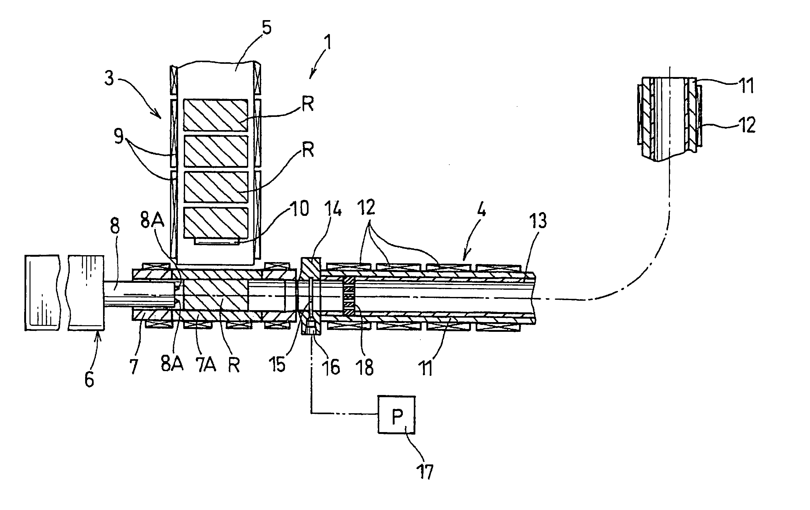
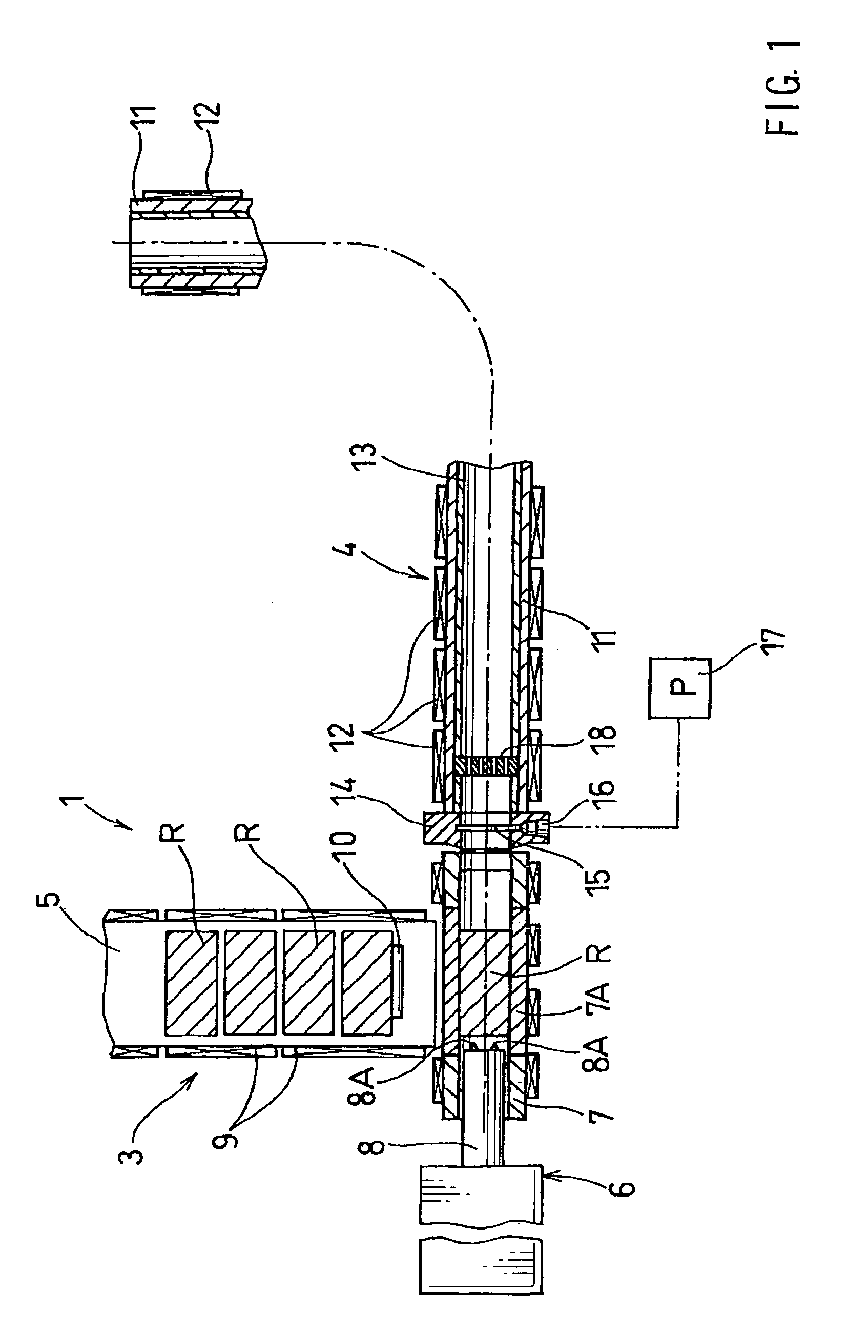
[0029]In one aspect of the present teachings, a vacuum-generating device (e.g., any appropriate device that can generate a reduced pressure) is preferably in communication with the interior of the heating structure. Therefore, during the melting operation, a substantial vacuum condition can be created within heating structure. Preferably, the vacuum-generating device (e.g., vacuum pump) may be coupled to the heating structure (e.g. a heating cylinder) at a position that is substantially adjacent to the inlet of the heating structure.

[0030]In other representative embodiment of the present teachings, the heating structure may have a substantially cylindrical shape (i.e., a heating cylinder) and the materials may be supplied into the heating cylinder in forms of rods that have a predetermined length. The rods may be sequentially pushed into the heating cylinder and the rods will melt as they move along the length of the heating cylinder.

[0031]A squeezing device or member, such as a rin...


PUM

PropertyMeasurementUnit
Pressureaaaaaaaaaa
Diameteraaaaaaaaaa

Abstract

A molten material supply unit includes a heating cylinder. The heating cylinder may receive and heat the material in a substantially vacuum condition. A molding apparatus may include a pressurizing and charging unit in addition to the molten material supply unit. The pressurizing and charging unit is adapted to receive the melted material from the molten material supply unit and to charge the melted material into a die under pressure.

Description

[0001]This application is a division of Ser. No. 09 / 953,433 filed Sep. 17, 2001, now abandoned.BACKGROUND OF THE INVENTION[0002]1. Field of the Invention[0003]The present invention relates to molten material supply units, and may be, for example, advantageously utilized to melt materials, such as metals and / or mixtures of metal and plastic, that have relatively high melting points. The present invention also relates to molding apparatus (e.g. molding dies) that include such molten material supply units.[0004]2. Description of the Related Art[0005]Die-cast molds (machines) are typically used in order to mold metals into articles of manufacture. Molten metals, such as molten aluminum alloys and magnesium alloys, are usually melted in a blast furnace and then transferred to the die while being exposed to air. Thereafter, the molten metals are injected under pressure into the die. Generally speaking, die-cast molds utilize a piston-cylinder mechanism to pressurize the molten metals, so ...

Claims


Application Information

Patent Timeline
IPC IPC(8): B22D17/08B22D17/00B22D17/28B22D17/30B29C45/46B29C45/53B29C45/63B29C45/72
CPCB22D17/007B22D17/28B22D17/30B29C45/53B29C45/63B29C45/72B29C45/462Y10S164/90
Inventor YAMADA, FUJIO
Owner FUJI TECH SYST CO LTD
Why Eureka
Try Eureka