Excavator demolition attachment with interchangeable jaw assemblies

a technology of jaw assembly and excavating attachment, which is applied in the direction of mechanical machines/dredgers, soil shifting machines/dredgers, grain treatment, etc., can solve the problems of exposing operating personnel to injury, main pivot pins that cannot be made very heavy and durable, and main pivot pin contamination. to achieve the effect of strengthening the main pivot pin

Active Publication Date: 2007-10-23
GENESIS ATTACHMENTS
View PDF65 Cites 52 Cited by
  • Summary
  • Abstract
  • Description
  • Claims
  • Application Information

AI Technical Summary

Benefits of technology

[0009]A principal object and advantage of the present invention is that a jaw assembly can be removed as a unit without removing the main pivot pin from the jaw assembly.
[0010]Another principal object and advantage of the present invention is that the main pivot pin can be made stronger than in shears where the main pivot pin must be removed to detach the jaws from the boom structure.
[0011]Another principal object and advantage of the present invention is that the main pivot pin is not subject to contamination because it is never removed from the jaws.
[0012]Another principal object and advantage of the present invention is that the jaws have hooks which mate with slots on the boom structure, so that the jaws may simply be placed on the ground and the boom structure manipulated to hook onto the jaws.
[0013]Another principal object and advantage of the present invention is that the jaw assembly is attached to the boom structure by a hydraulically activated lock pin which is a part of the boom structure and thus easily used to secure the jaw assembly to the boom structure.
[0014]Another principal object and advantage of the present invention is that the jaw assembly may rest on the ground and be easily mounted to the boom structure by hooking the jaw assembly to the boom structure then lifting the jaw assembly to make contact with a stop on the boom structure.

Problems solved by technology

One problem with shears such as this is that the main pivot pin cannot be made very heavy and durable, as it must be slid out from the jaws.
Also, the main pivot pin was subject to contamination when changing jaws.
Furthermore, removing the main pivot pin exposed operating personnel to injury, as either the pin itself or the jaws might cause injury as the pin was removed.

Method used


Image

  • Excavator demolition attachment with interchangeable jaw assemblies
  • Excavator demolition attachment with interchangeable jaw assemblies
  • Excavator demolition attachment with interchangeable jaw assemblies

Examples


Embodiment Construction

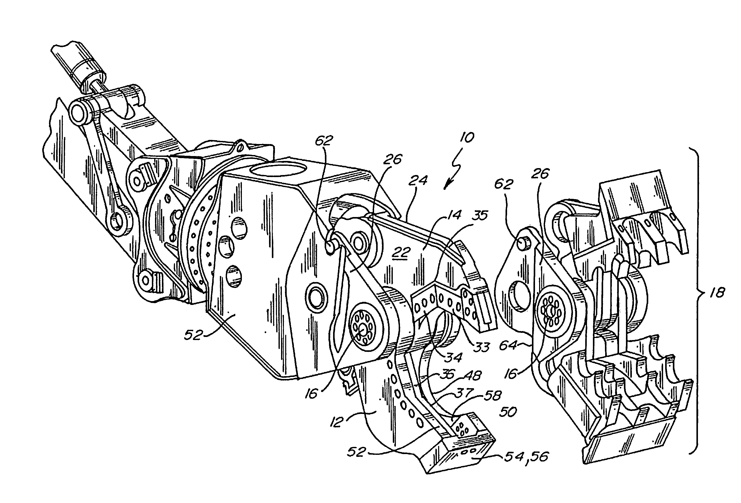
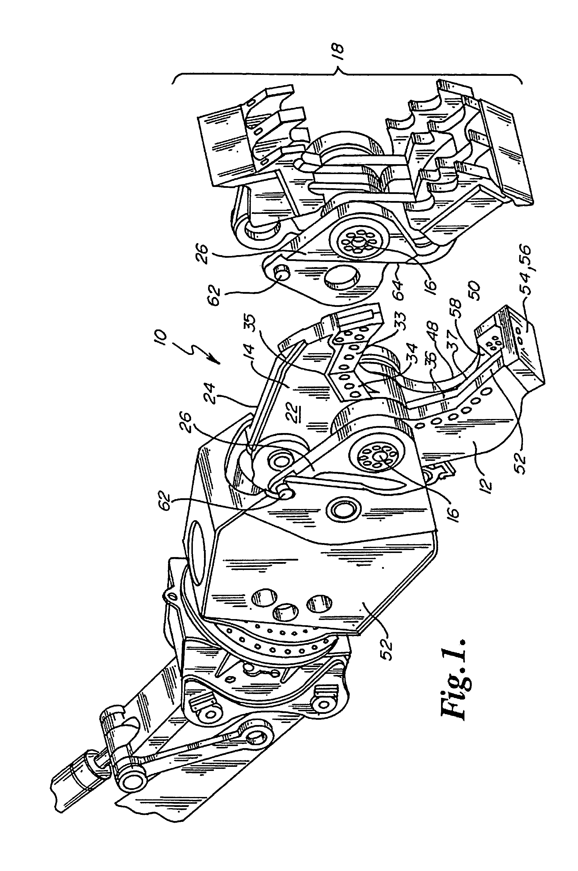
[0034]The heavy-duty demolition apparatus of the present invention is generally referred to in the Figures as reference numeral 10.

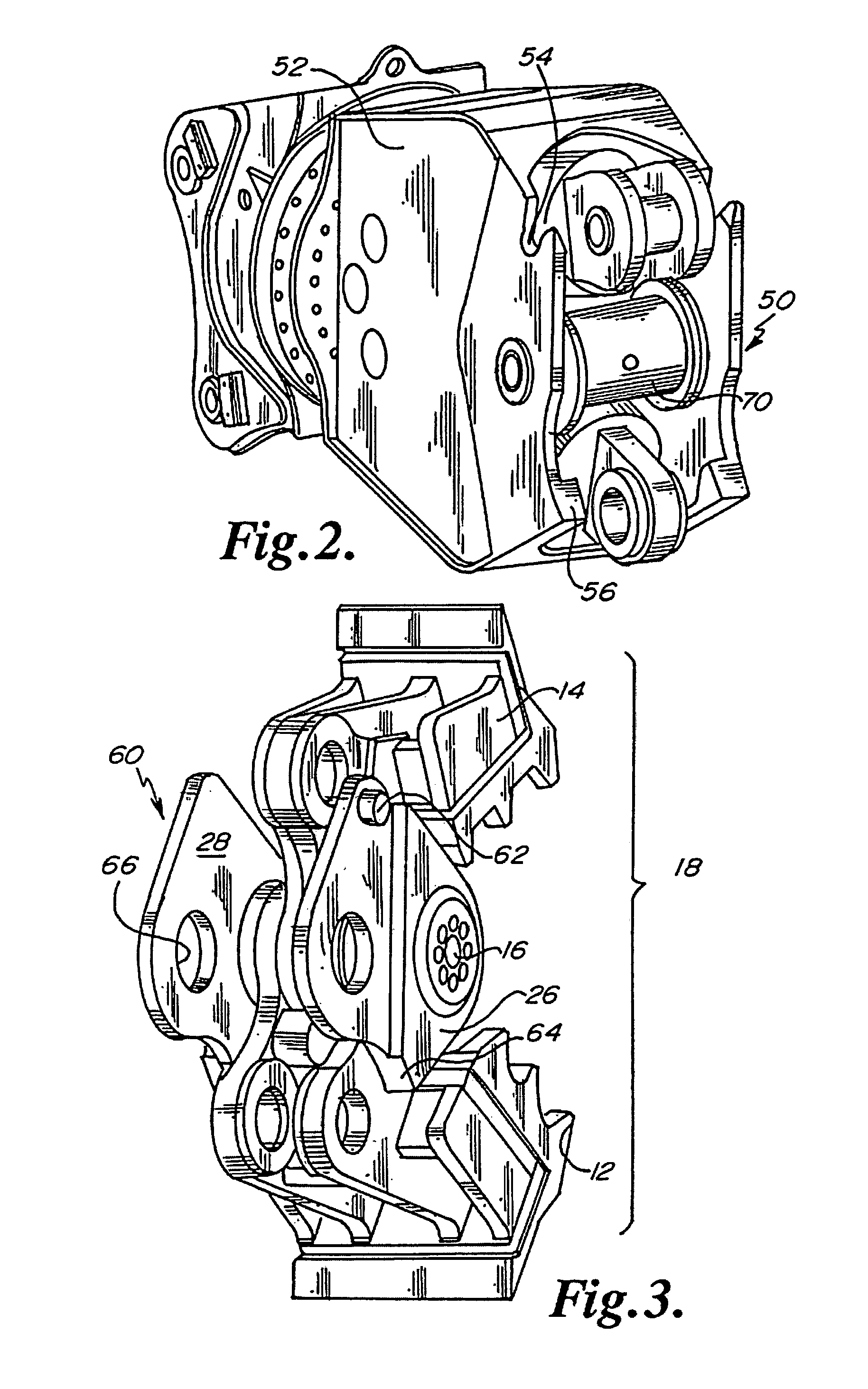
[0035]Referring to FIG. 1, the heavy-duty demolition apparatus 10 has a lower jaw 12, an upper jaw 14, and pivot pin 16 interconnecting the lower jaw 12 and upper jaw 14. The lower jaw 12, upper jaw 14, and pivot pin 16 comprise a unitary jaw assembly 18.

[0036]The upper jaw 14 has a first side 22, and a second side 24. The lower jaw 12 has a first mounting plate 26 adjacent the first side 22, and a second mounting plate 28 (FIG. 3) adjacent the second side 24. The first mounting plate 26 and second mounting plate 28 receive the pivot pin 16 between them.

[0037]The upper jaw 14 typically has upper shear blades 33 and 34 meeting at apex 35 and the lower jaw 12 typically has lower shear blades 36 and 37 extending along each other for shearing a work-piece when the upper shear blades 33 and 34 are closed upon the lower shear blades 36 and 37. Preferably, the ...


PUM


Abstract

A heavy-duty demolition apparatus for attachment to the boom structure of an excavator, the apparatus having interchangeable jaw sets. The apparatus includes a unitary jaw assembly, having a pair of pivoting jaws connected by a main pivot pin; a first adaptor on the boom structure; a second adaptor on the jaw assembly, the second adaptor engaging the first adaptor, so that the jaw assembly can be easily removed as a unit from the boom structure and another jaw assembly installed on the boom structure; and a lock pin fixed to the first adapter and engaging the second adapter to maintain the jaw assembly in locked relationship to the boom structure. Because of the structure of the apparatus, the distance between the attachment point of the hydraulic ram on the boom structure and the main pivot point of the jaw assembly can be varied between interchangeable jaw assemblies.

Description

BACKGROUND OF THE INVENTION[0001]A fuller understanding of the operation of the demolition apparatus of the present invention may be achieved by studying U.S. Pat. No. 4,519,135, hereby incorporated by reference. This invention relates to a heavy duty demolition apparatus, especially adapted to be mounted on a rigid boom of a mobile vehicle and particularly adapted to be mounted on the dipper stick of an excavator, and particularly to such an apparatus with interchangeable jaws.[0002]Heavy duty shears of the type that are powered by hydraulic cylinders are proving more and more useful in handling scrap and especially metal scrap of all sorts. Such scrap comes in many different forms, and may be in the form of pipes made of steel or soft iron or cast iron, ranging in sizes from 2 inches or smaller, and up to 8 or 10 inches in diameter or larger; structural beams such as I-beams, channels, angle beams in a large range of sizes, up to 8 or 10 inches across and larger; rods and heavy ca...

Claims


Application Information

Patent Timeline
Patent Type & Authority Patents(United States)
IPC IPC(8): B02C1/02
CPCE02F3/965E02F3/3609E02F3/96E02F3/36
Inventor CHRISTENSON, ROSS D.
Owner GENESIS ATTACHMENTS
Why Eureka
Try Eureka