Torsion beam suspension

a technology of torsion beam and suspension, which is applied in the direction of resilient suspension, interconnection system, vehicle components, etc., can solve the problems of weight and cost disadvantage, fear of significantly reducing the strength of torsion beam, etc., and achieve the effect of high durability

Inactive Publication Date: 2007-10-23
F TECH INC
View PDF3 Cites 25 Cited by
  • Summary
  • Abstract
  • Description
  • Claims
  • Application Information

AI Technical Summary

Benefits of technology

[0007]The present invention has been achieved in view of the above circumstances, and has an object to provide a torsion beam suspension having a high durability without reducing strength of a torsion beam, in which an abrupt increase in torsional rigidity, that is, geometrical moment of inertia at a gusset inner end portion of the torsion beam is suppressed.

Problems solved by technology

Therefore, there is rather a fear of significantly reducing the strength of the torsion beam because of cooperation between the stress concentration on the fragile portion and the stress concentration on the inner end portion of the gusset.
If the plate thickness of the torsion beam is increased to compensate for the reduction in strength, the weight and cost are disadvantageously increased.

Method used


Image

  • Torsion beam suspension
  • Torsion beam suspension
  • Torsion beam suspension

Examples


Embodiment Construction

[0022]Preferred embodiments of the present invention will now be described based on the attached drawings.

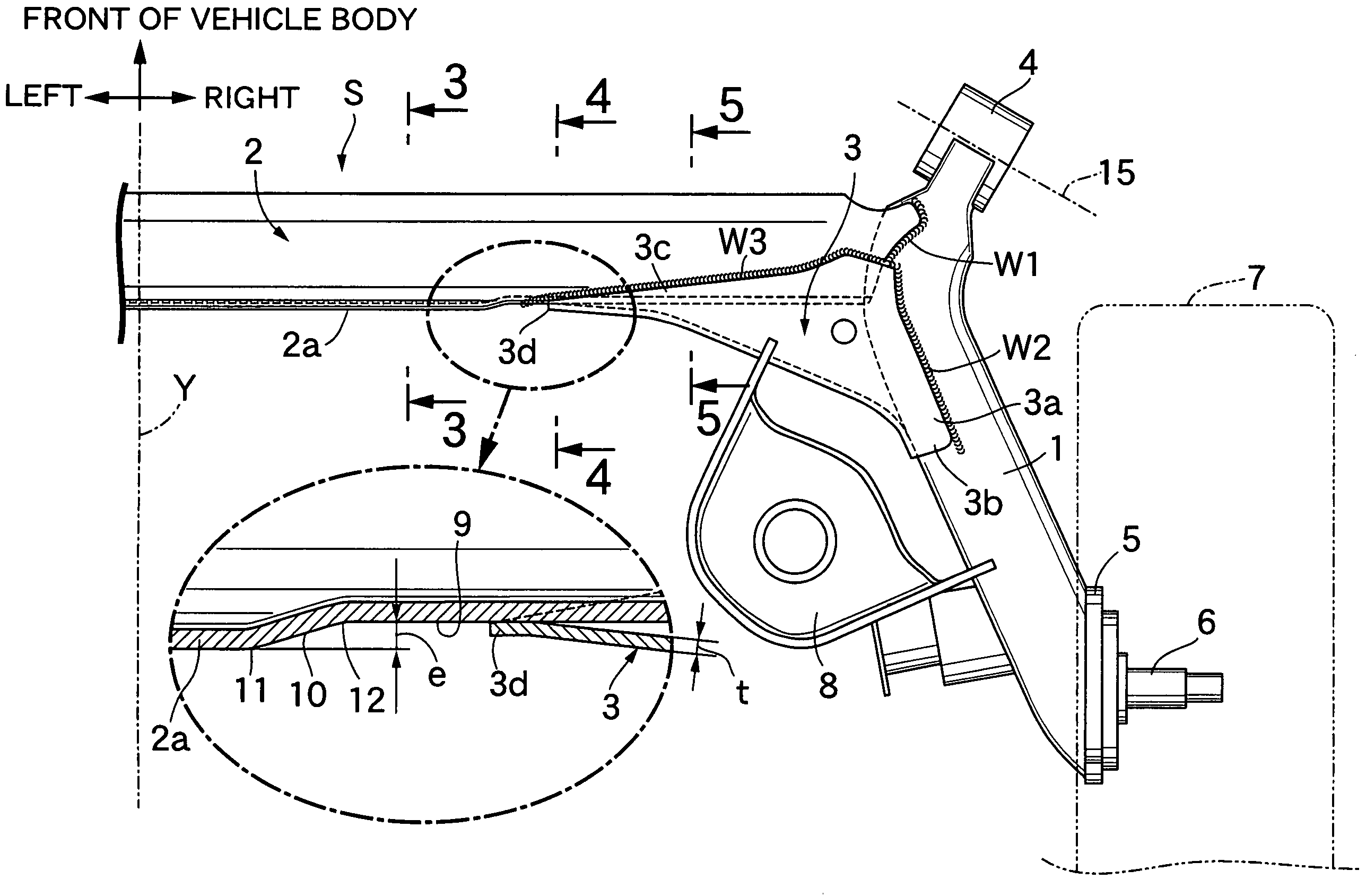
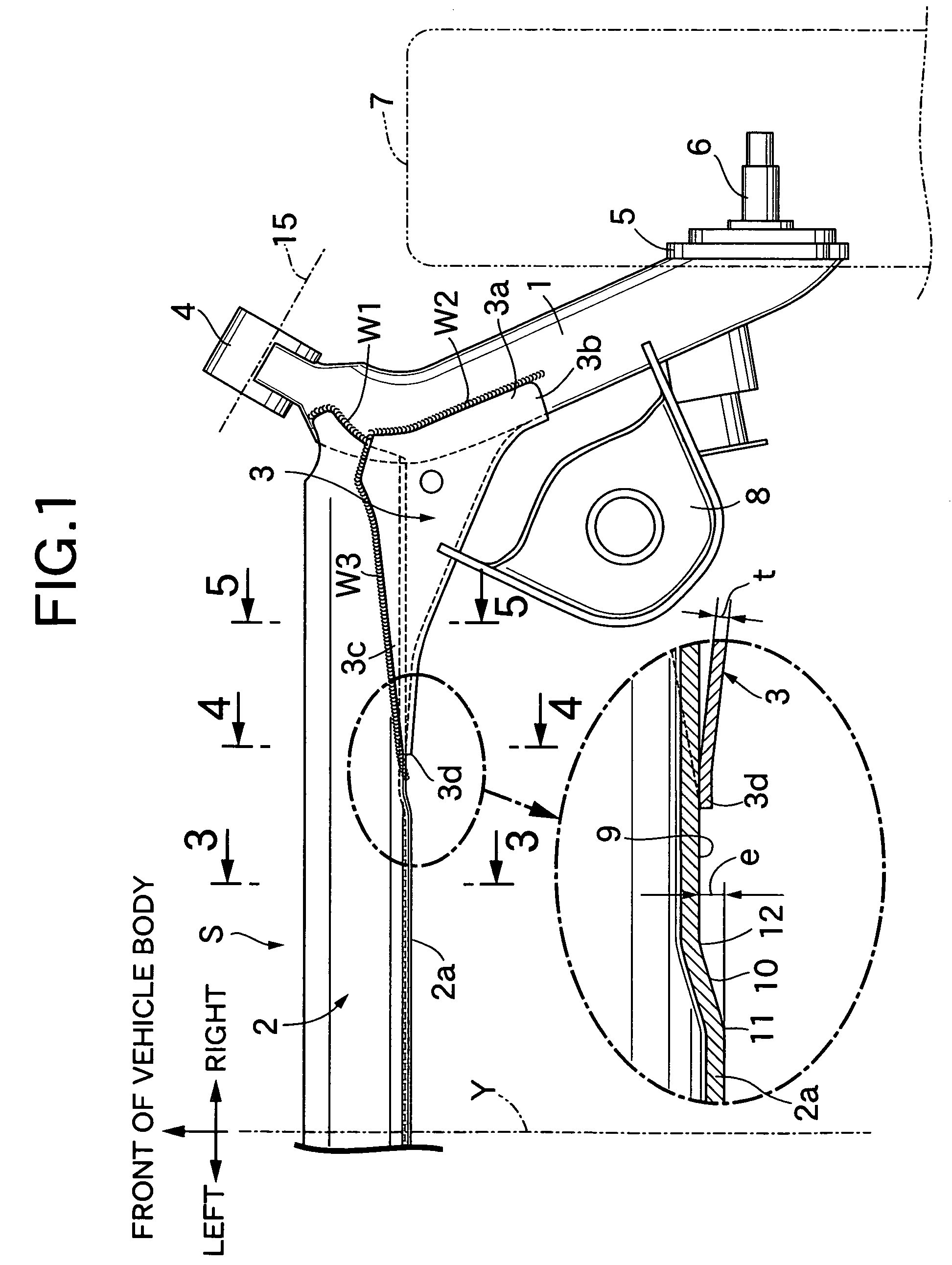
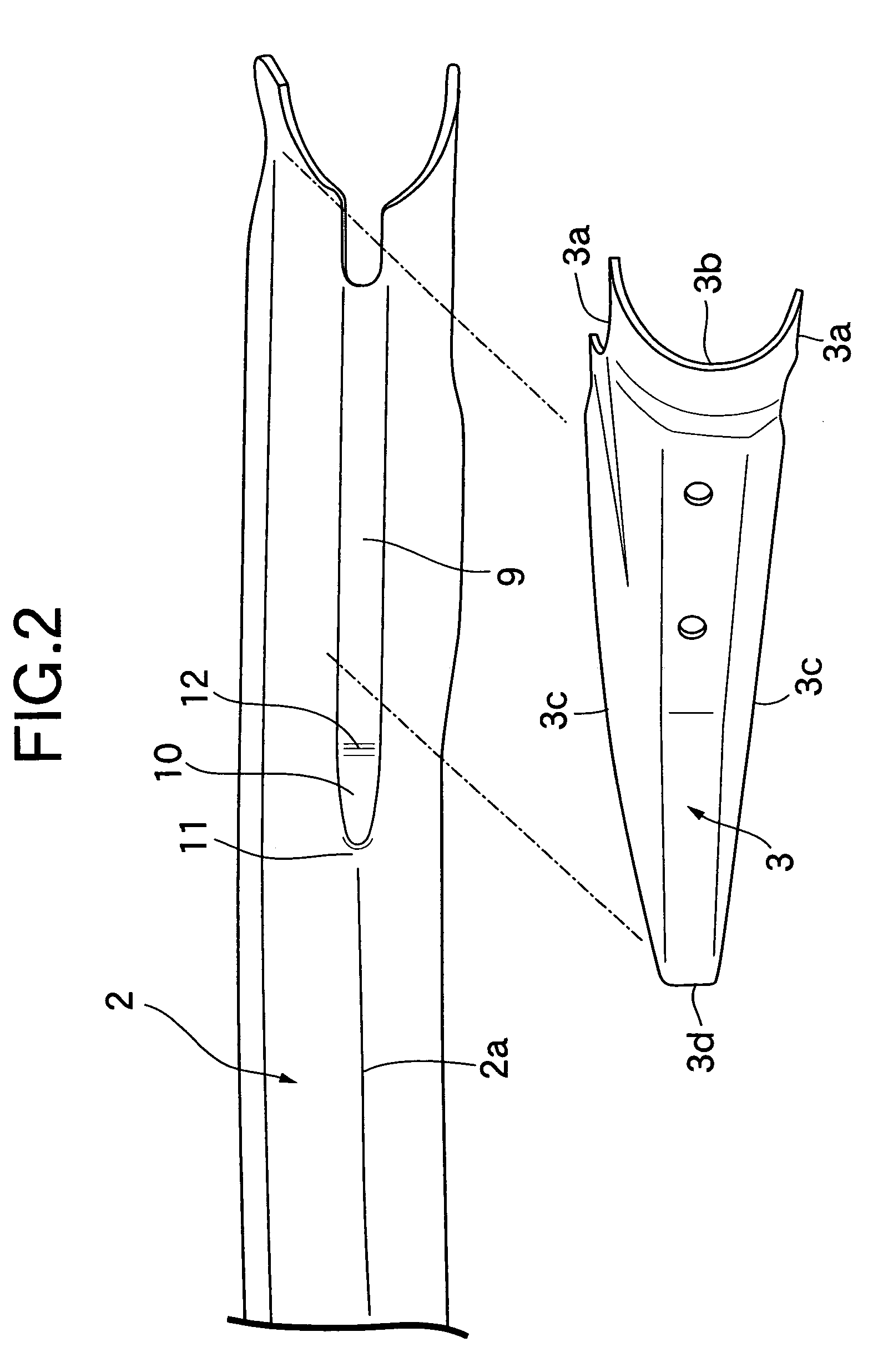
[0023]First, in FIG. 1, a torsion beam suspension S which suspends left and right rear wheels 7 and 7 is mounted on a vehicle body (not shown) of an automobile. The torsion beam suspension S has a laterally symmetric structure with respect to a center line Y extending in a longitudinal direction of the vehicle body. The torsion beam suspension S comprises: a pair of left and light trailing arms 1 and 1 extending in the longitudinal direction of the vehicle body; a torsion beam 2 which extends in a lateral direction of the vehicle body, has opposite ends connected by welds W1 to the left and right trailing arms 1 and 1, and torsionally deforms when the trailing arms 1 and 1 swing in opposite phases; and gussets 3 which are connected by welds W2 and W3 to inner side surfaces of connecting portions between the trailing arms 1 and the torsion beam 2.

[0024]A cylindrical arm support t...


PUM


Abstract

In a torsion beam suspension including: a pair of left and right trailing arms 1; a torsion beam 2 providing connection between the trailing arms 1; and gussets 3 which are U-shaped in section and substantially triangular in plane view and which are welded to inner side surfaces of connecting portions between the trailing arms 1 and the torsion beam 2, seat surfaces 9 are formed by crushing at left and right opposite end portions of a rear wall 2a of the torsion beam 2, the seat surfaces 9 being offset forward from a general outer surface of the rear wall 2a by an amount e larger than a plate thickness t of the gussets 3, and each gusset 3 includes an inner end edge portion 3d superposed on an intermediate portion in a lateral direction of the seat surface 9, and upper and lower front edge portions 3c, 3c connected by a weld W3 to upper and lower portions of an outer surface of the torsion beam 2. Thus, in the torsion beam, an abrupt increase in torsional rigidity is suppressed in the gusset inner end portion without reducing strength of the torsion beam to alleviate stress concentration, thereby providing a torsion beam suspension having a high durability.

Description

BACKGROUND OF THE INVENTION[0001]1. Field of the Invention[0002]The present invention relates to a torsion beam suspension of an automobile, and particularly relates to an improvement of a torsion beam suspension comprising: a pair of left and right trailing arms which are pivotally supported at their front end portions on a vehicle body, and which support wheels at their rear end portions; a torsion beam which has left and right opposite end portions connected to the trailing arms by welds, and which causes torsion when the trailing arms swing in opposite phases; and gussets which are U-shaped in section and substantially triangular in plane view, and which are connected by welds to inner side surfaces of connecting portions between the trailing arms and the torsion beam.[0003]2. Description of the Related Art[0004]Such a torsion beam suspension is already known as disclosed in Japanese Patent Application Laid-open No. 10-236123.[0005]In the torsion beam suspension, gussets which a...

Claims


Application Information

Patent Timeline
Patent Type & Authority Patents(United States)
IPC IPC(8): B60G11/20
CPCB60G21/051B60G2200/23B60G2206/8201B60G2206/8102B60G2206/014
Inventor INOUE, MITSURUKIKUCHI, FUMIO
Owner F TECH INC
Why Eureka
Try Eureka