Power line communication device for vehicle

a communication device and power line technology, applied in the direction of electric devices, single ac network with different frequencies, program control, etc., can solve the problems of increasing the communication error rate (bit error rate), communication becomes unstable, communication errors, etc., and achieve the effect of improving communication quality

Inactive Publication Date: 2007-10-23
YAZAKI CORP
View PDF10 Cites 29 Cited by
  • Summary
  • Abstract
  • Description
  • Claims
  • Application Information

AI Technical Summary

Benefits of technology

[0010]The present invention is achieved in light of the above problems and objects thereof are to stabilize communication which is established by signals sup...

Problems solved by technology

Thereby the input noise influences the signals sent and received between the respective ECUs and causes communication errors.
This causes a problem of increasi...

Method used


Image

  • Power line communication device for vehicle
  • Power line communication device for vehicle
  • Power line communication device for vehicle

Examples


Embodiment Construction

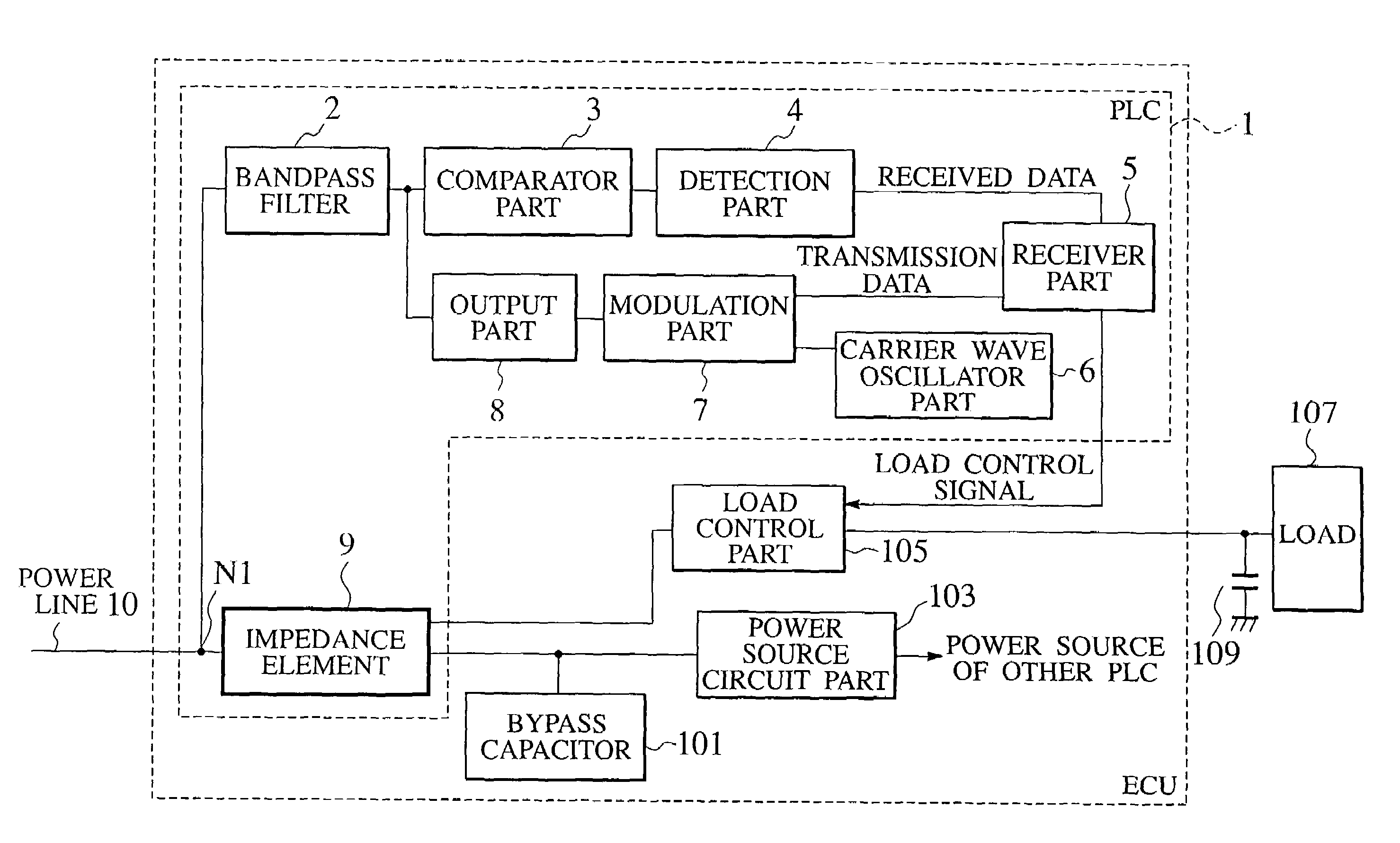
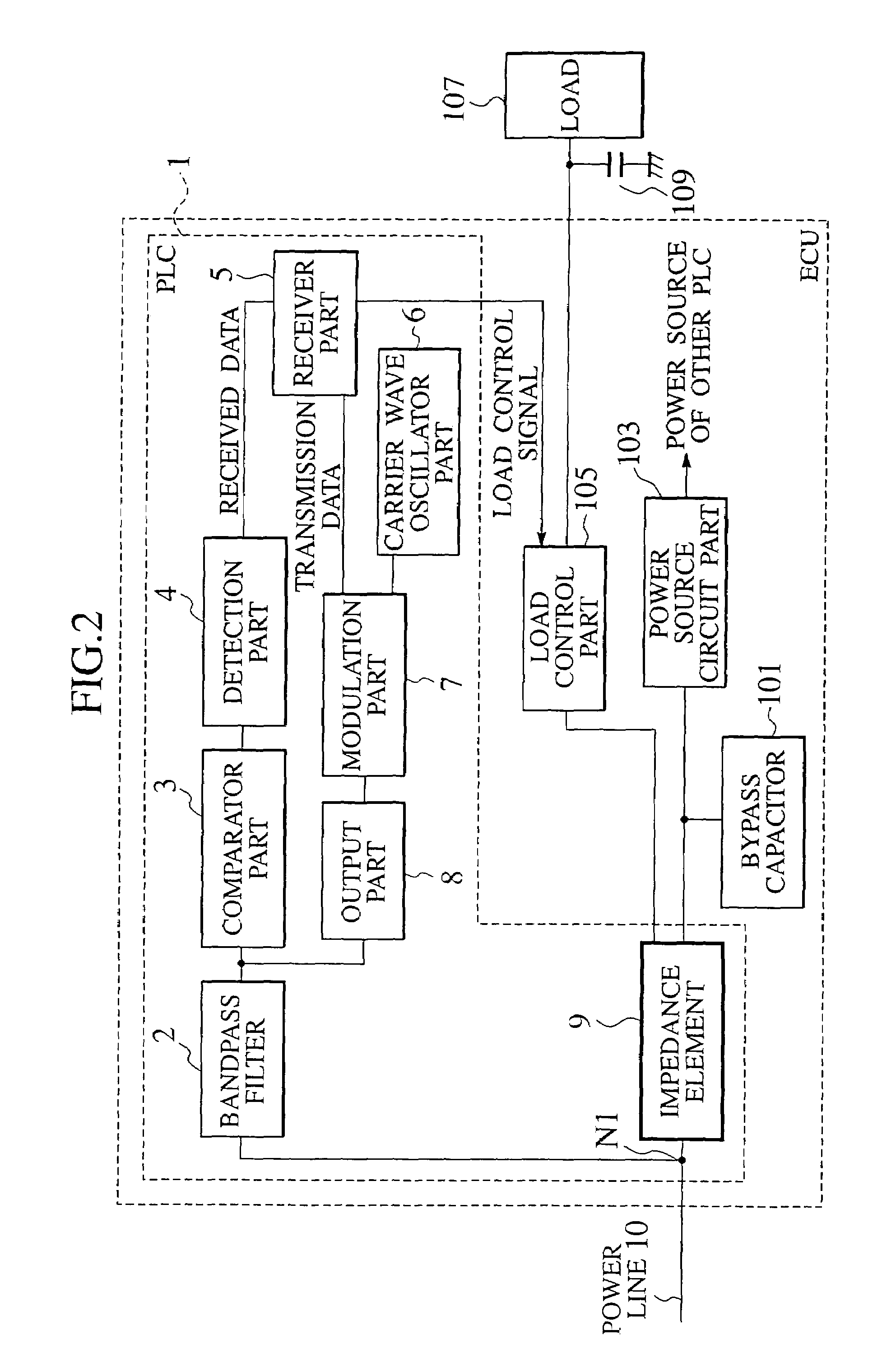
[0022]FIG. 2 is a block diagram of an ECU including a power line communication device for a vehicle (hereinafter called “PLC”) according to an embodiment of the present invention. The PLC 1 included in the ECU is provided with a bandpass filter 2, a comparator part 3, a detection part 4, a receiver part 5, a carrier oscillator part 6, a modulation part 7, an output part 8 and an impedance element 9.

[0023]A bypass capacitor 101, a power source circuit part 103 and a load control part 105 included in the ECU, as well as a load 107 and a capacitor 109 for noise reduction, connected with the load 107, have the same functions as the above proposed ECU and detailed description will be omitted.

[0024]Signals which are superimposed on a supply voltage applied to a power line 10 so as to establish communication with the other ECUs are input into the bandpass filter 2. Noise components of low frequencies and high frequencies are filtered out of the input signals by means of the bandpass filter...


PUM


Abstract

A power line communication device for a vehicle is provided with an internal electronic control unit connected to a connection point on a power line, which communicates with an external electronic control unit by a communication signal superimposed on a supply voltage applied to the power line, and an impedance element inserted between the connection point and an external load. The impedance element suppresses attenuation of the communication signal.

Description

BACKGROUND OF THE INVENTION[0001]1. Field of the Invention[0002]The present invention relates to a power line communication device for a vehicle, which superimposes various signals on a power line so as to establish communication between devices equipped in the vehicle.[0003]2. Description of the Related Art[0004]These days, many technical advantages are offered to vehicles and therefore a vehicle has a plurality of electronic control units (hereinafter called “ECU”) on board. The ECUs control power windows, lamps and side mirrors as well as an engine and a transmission. The ECUs are connected with each other via private signal lines or common data buses and communicate with each other so that the ECUs operate cooperatively with each other.[0005]Recently, the signal lines interconnecting the ECUs have been increased because the number of the ECUs has become larger and the number of signals has become larger due to complicated control. Thereby a structure of a wiring harness for a ve...

Claims


Application Information

Patent Timeline
IPC IPC(8): H04M1/30H04B3/54H04B3/56
CPCH04B3/548H04B3/56H04B2203/5491H04B2203/547H04B2203/5416
Inventor YANAGIDA, YOSUGIMOTO, TERUMITSU
Owner YAZAKI CORP
Why Eureka
Try Eureka