High performance interface logic architecture of an intermediate network node

a logic architecture and intermediate network technology, applied in the field of communication networks, can solve the problems of affecting the efficiency of packet processing functions of the pre, affecting the construction of a central aggregation point within the aggregator, such as the pre, would be quite expensive, so as to improve the qos delivery of the device, improve congestion management and latency, and increase bandwidth requirements

Active Publication Date: 2007-10-23
CISCO TECH INC
View PDF25 Cites 21 Cited by
  • Summary
  • Abstract
  • Description
  • Claims
  • Application Information

AI Technical Summary

Benefits of technology

[0019]Architectural features of the aggregation router include implemention of a conventional multi-level switching arrangement within a single router and the ability of the PRE to support and accommodate substantially large bandwidth requirements. In the illustrative embodiment, the aggregation router can sup

Problems solved by technology

In the absence of a single ASIC implementation of the interface logic, the efficiency of packet processing functions by the PRE would

Method used


Image

  • High performance interface logic architecture of an intermediate network node
  • High performance interface logic architecture of an intermediate network node
  • High performance interface logic architecture of an intermediate network node

Examples


Embodiment Construction

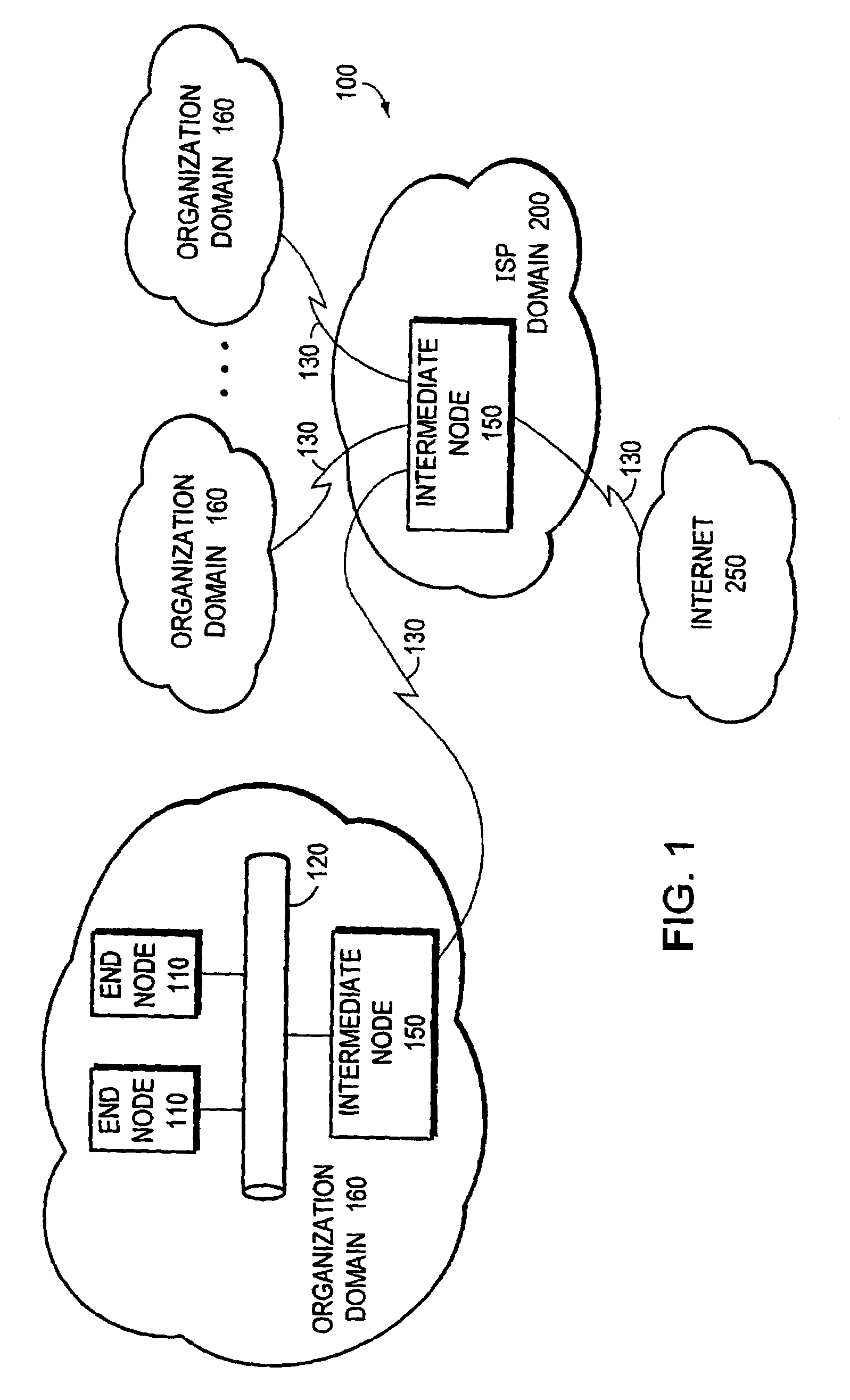
[0027]FIG. 1 is a schematic block diagram of a computer network 100 comprising a collection of communication links and segments connected to a plurality of nodes, such as end nodes 110 and intermediate nodes 150. The network links and segments may comprise local area networks (LANs) 120 and wide area network (WAN) links 130 interconnected by intermediate nodes 150, such as network switches or routers, to form an internetwork of computer nodes. These internetworked nodes communicate by exchanging data packets according to a predefined set of protocols, such as the Transmission Control Protocol / Internet Protocol (TCP / IP). It should be noted that other techniques / protocols, such as the Hypertext Transfer Protocol (HTTP), may be advantageously used with the present invention.

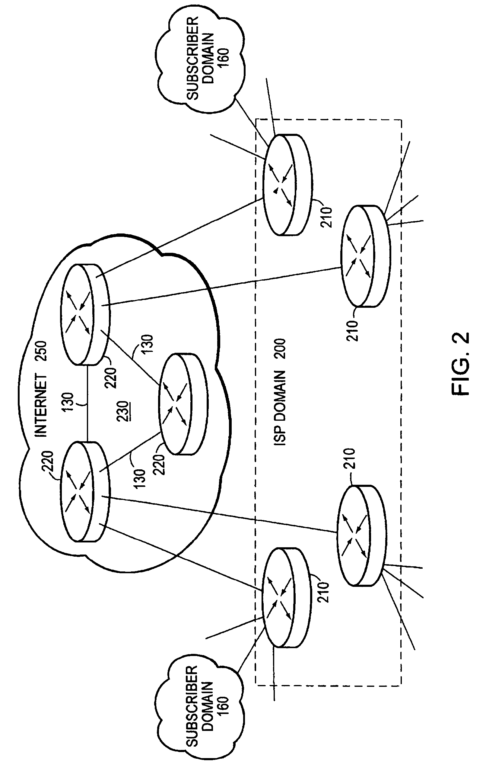
[0028]To interconnect their dispersed private computer networks and / or provide Internet connectivity, many organizations rely on the infrastructure and facilities of Internet service providers (ISPs) rather than pur...


PUM


Abstract

An aggregation router architecture comprises a plurality of line cards coupled to at least one performance routing engine (PRE) via an interconnect system. The line cards include input cards having input ports coupled to subscribers and at least one trunk card configured to aggregate packets received from the subscriber inputs over at least one output port. The PRE performs packet forwarding and routing operations, along with quality of service functions for the packets received from each input line card over the interconnect system. The interconnect system comprises a plurality of high-speed unidirectional (i.e., point-to-point) links coupling the PRE to each line card. The point-to-point links couple the line cards to a novel logic circuit of the PRE that is configured to interface the line cards to a packet buffer and a forwarding engine of the PRE.

Description

CROSS-REFERENCE TO RELATED APPLICATIONS[0001]The present invention is related to the following co-pending and commonly assigned U.S. patent applications:[0002]U.S. patent application Ser. No. 09 / 791,074 titled, Method and Apparatus for Controlling Packet Header Buffer Wrap Around in a Forwarding Engine of an Intermediate Network Node; and[0003]U.S. patent application Ser. No. 09 / 790,968 titled, Mapping Technique for Computing Addresses in a Memory of an Intermediate Network Node, each of which was filed on even date herewith and incorporated by reference as though fully set forth herein.FIELD OF THE INVENTION[0004]The present invention relates to communications networks and, in particular, to the architecture of an aggregation router used in a communications network, such as a computer network.BACKGROUND OF THE INVENTION[0005]A computer network is a geographically distributed collection of interconnected communication links and segments for transporting data between nodes, such as c...

Claims


Application Information

Patent Timeline
IPC IPC(8): H04L12/28
CPCH04L12/66
Inventor RACHEPALLI, MARUTHINGENDRA P.SIVAKOLUNDU, RAMESHPOTTER, KENNETH H.FEDORKOW, GUY C.MUNTZ, GARY S.
Owner CISCO TECH INC
Why Eureka
Try Eureka