Multi-color electrophoretic image display

a multi-color electrophoretic and image technology, applied in the field of multi-color electrophoretic image display, can solve the problems of limiting the number of applications where epids can be employed, and the art electrophoretic display

Inactive Publication Date: 2007-10-30
AU OPTRONICS CORP
View PDF26 Cites 22 Cited by
  • Summary
  • Abstract
  • Description
  • Claims
  • Application Information

AI Technical Summary

Benefits of technology

[0012]A color electrophoretic display comprising a plurality of cells each containing electrophoretic particles. Each of the cells in the plurality is capable of displaying at least one of three selected primary colors, when the particles in the cell are moved from a first rest position to a second display position on the cell. An electrode is coupled to each of the cells and is operative when biased to move the particles from the first rest position to the second display position thereby displaying primary colors in the second display position and causing the display to provide full color capability according to particle position in the cells.

Problems solved by technology

One drawback associated with most prior art electrophoretic displays is that they are monochromatic.
This drawback severely limits the number of applications where EPIDs can be employed.

Method used


Image

  • Multi-color electrophoretic image display
  • Multi-color electrophoretic image display
  • Multi-color electrophoretic image display

Examples


first embodiment

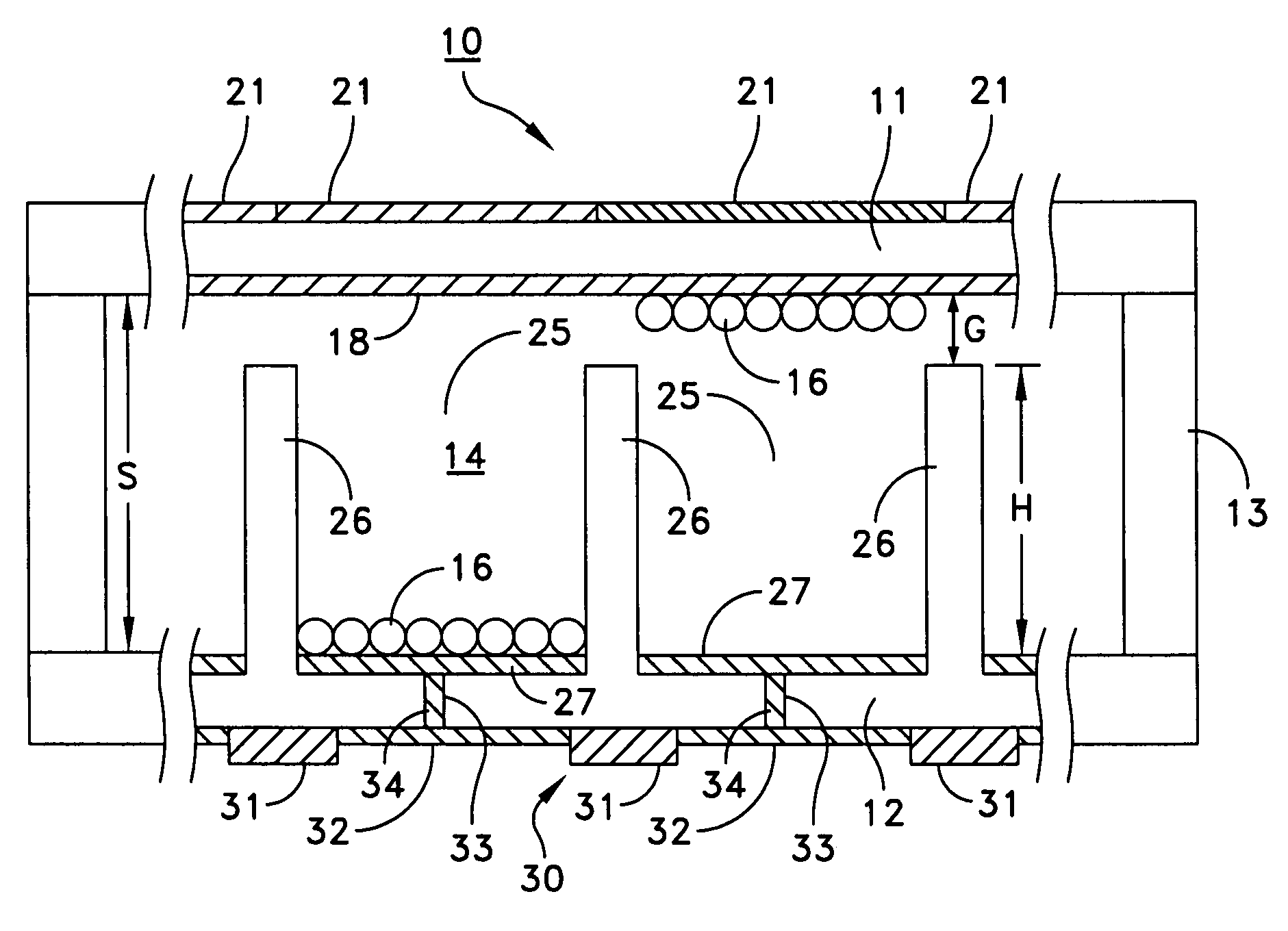
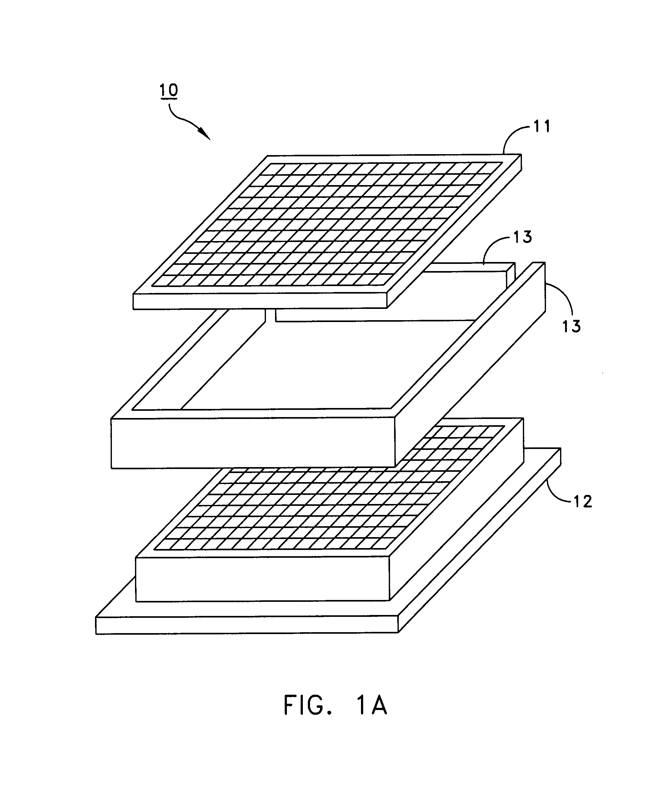
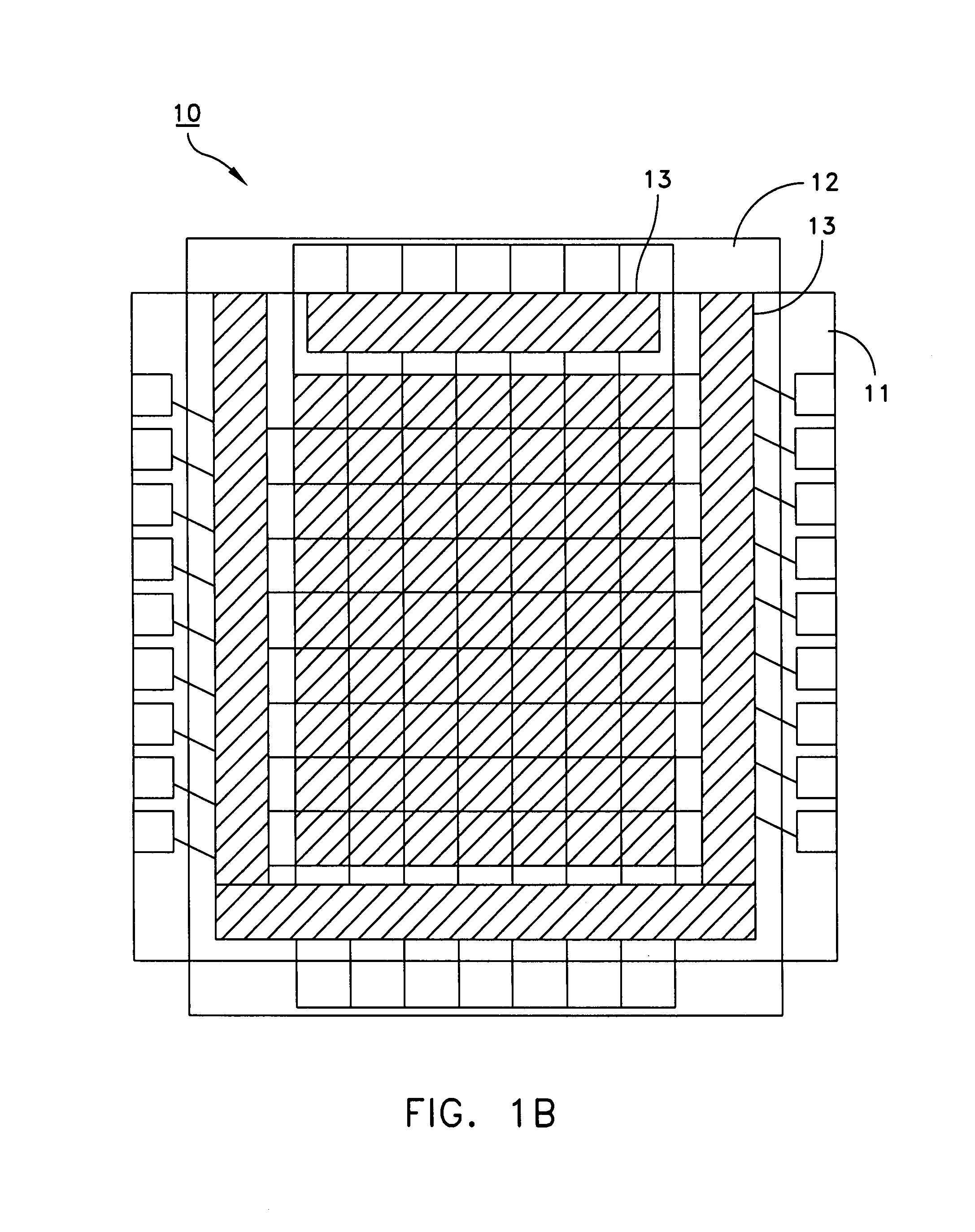
[0031]FIGS. 1A and 1B collectively show a multi-color electrophoretic image display (EPID) 10 according to the invention. The EPID 10 comprises a pair of parallel electrodes 11, 12 sealingly assembled together with spacers 13 to form a liquid and gas sealed enclosure having a small space S between the electrodes 11, 12 (FIG. 4), and an electrophoretic fluid 14 filling the space S between the electrodes. The electrophoretic fluid 14 is conventional, comprising a dielectric liquid of a dark color, such as a blue or red, having suspended therein millions of polymer / pigment composite dielectric particles 16 (electrophoretic particles 16) of a light color, such as white or yellow, which can be charged in accordance with known techniques. The EPID 10 is typically rectangular in shape, although other geometrical configurations can be employed as well.

[0032]Electrode 11, referred to hereinafter as anode 11, is constructed from a generally planar sheet of transparent plastic or glass. As sho...

third embodiment

[0041]FIGS. 7A-7C collectively illustrate the EPID 70 according to the invention. In this embodiment, the cathode 12 essentially omits the cell side walls which project from the inner surface 23 thereof in the previous embodiments. This allows the drive circuit 30, TO which includes the electrically conductive metal lines 32 that electrically interconnect the diodes or transistors 31 disposed between the pixels, to be formed on the inner surface 23 of the cathode 12 along with the electrode pads 27 so that the electrically conductive through-holes used in the previous embodiments can be eliminated. Electrically conductive contact pads 71, which connect the drive diodes or transistors 31 to a driver chip, are also formed on the inner surface 23 of the cathode 12 adjacent opposing edges of the cathode 12.

fourth embodiment

[0042]FIGS. 8A-8C collectively illustrate an EPID 60 according to the invention. In this embodiment, the EPID 60 is constructed by combining three individual EPIDs 61, 62, 63 together in a face-to-face manner. The front, middle, and rear EPIDs 61, 62, 63 can be constructed essentially as described above in the previous embodiments, but without the filter arrays. Each EPID 61, 62, 63 contains electrophoretic particles preferably of one of the primary colors red, blue, and green. For example, EPID 61 can contain red particles, EPID 62 can contain blue particles, and EPID 63 can contain green particles. Thus, the front EPID 61 displays only red light, the middle EPID 62 displays only blue light, and the rear EPID 63 displays only green light.

[0043]Further, the cells or pixels 64, 65, 66 of the EPIDs 61, 62, 63 are oriented so that the light produced by the cells or pixels 65, 66 of the middle and rear EPIDs 62, 63 can be view through the front EPID 61. This can be accomplished, as show...


PUM

PropertyMeasurementUnit
thicknessaaaaaaaaaa
thicknessaaaaaaaaaa
colorsaaaaaaaaaa

Abstract

A color electrophoretic display including a plurality of cells each containing electrophoretic particles. Each of the cells in the plurality is capable of displaying at least one of three selected primary colors, when the particles in the cell are moved from a first rest position to a second display position on the cell. An electrode is coupled to each of the cells and is operative when biased to move the particles from the first rest position to the second display position thereby displaying primary colors in the second display position and causing the display to provide full color capability according to particle position in the cells.

Description

FIELD OF THE INVENTION[0001]This invention relates to electrophoretic image displays and, more particularly, to a multi-color electrophoretic image display.BACKGROUND OF THE INVENTION[0002]The electrophoretic effect is well known in the art as evidenced by the many patents and articles which describe this effect. In essence, the electrophoretic effect operates on the principle that when certain particles are electrically charged to a particular polarity, the charged particles will migrate away from a surface charged to the same polarity as the particles and toward a surface charged to a polarity which opposite to that of the charged particles. For example, particles which are positively charged will migrate away from a positively charged surface and towards a negatively charged surface.[0003]Display devices which utilize the electrophoretic effect are commonly known as electrophoretic image displays (EPIDs). EPIDs are very well known in the art. The following patents issued to Frank...

Claims


Application Information

Patent Timeline
Patent Type & Authority Patents(United States)
IPC IPC(8): G09G3/34G02F1/167G02F1/1677
CPCG02F1/167G09G3/3446G09G3/2003G02F1/133514G02F2001/1672G09G2300/0426G09G2300/0408G02F1/1681G02F1/1677
Inventor DISANTO, FRANK J.KRUSOS, DENIS A.HOU, WEI-HSIN
Owner AU OPTRONICS CORP
Why Eureka
Try Eureka