Optical network termination with automatic determination of geographic location

a technology of optical network termination and geographic location, applied in the field of passive optical network, can solve problems such as security risks in the mechanism of manual access to the on

Active Publication Date: 2007-10-30
ALCATEL LUCENT SAS
View PDF8 Cites 127 Cited by
  • Summary
  • Abstract
  • Description
  • Claims
  • Application Information

AI Technical Summary

Problems solved by technology

However, any such mechanism which provides manual access to the ONT represents a security risk, because the access port that is used to provide the site identifier / geographic location information is also available to unauthorized users.

Method used


Image

  • Optical network termination with automatic determination of geographic location
  • Optical network termination with automatic determination of geographic location

Examples


Embodiment Construction

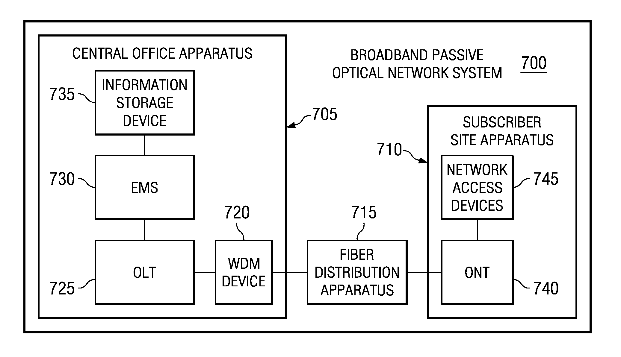
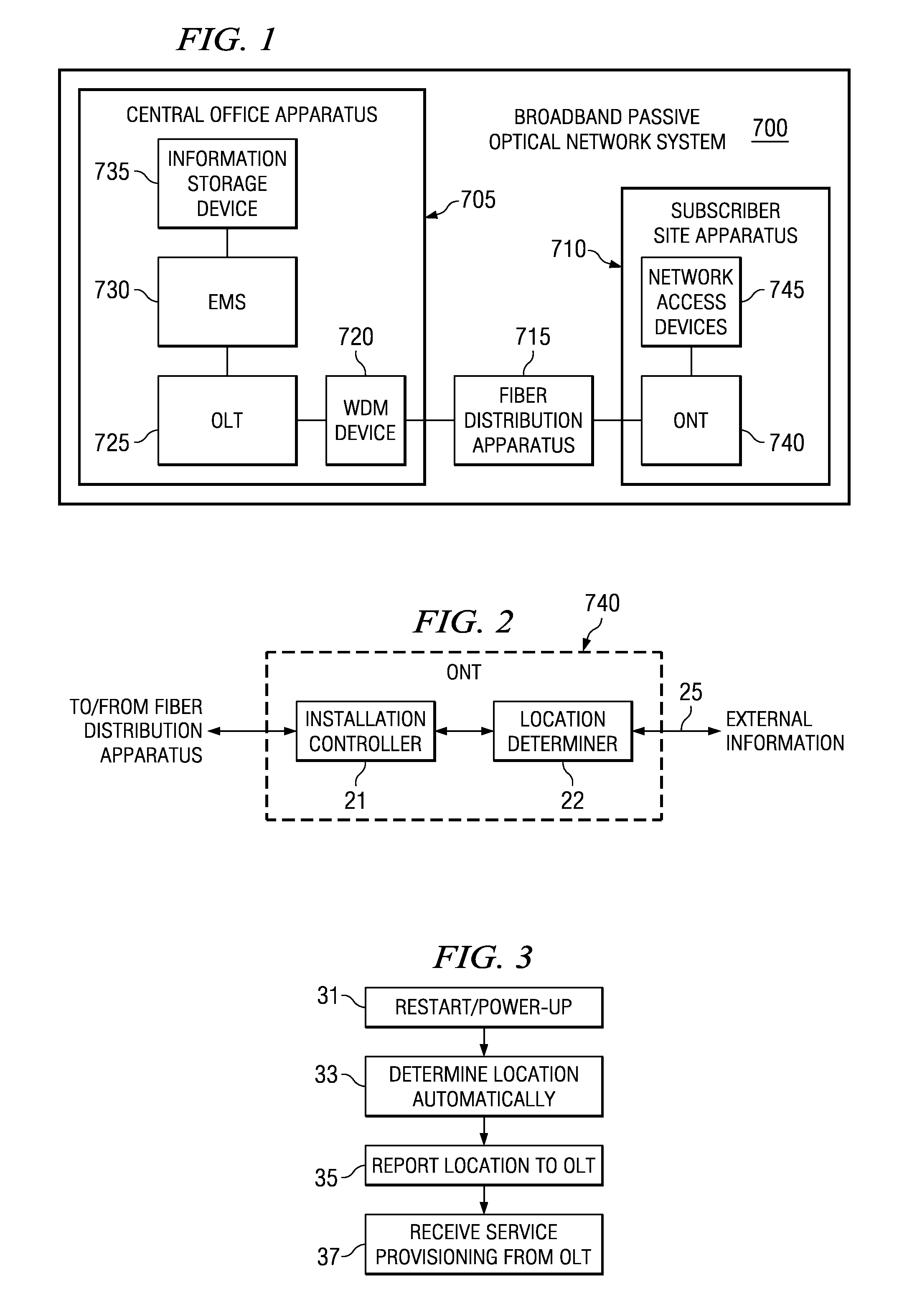
[0013]Referring now to FIG. 1, a Broadband Passive Optical Network (BPON) system 700 capable of carrying out the methods processes and operations disclosed herein is depicted. The BPON system 700 includes a central office apparatus 705, a subscriber site apparatus 710 and a fiber distribution apparatus 715 connected therebetween. Information is transmitted bi-directionally between the central office apparatus 705 and the subscriber site apparatus 710 via the fiber distribution network 715.

[0014]A BPON system, the current global standard for passive optical networking systems, is a combination of PON and Wavelength Division Multiplexing (WDM) solutions. PON enables the shared use of fiber for services such as data voice and video over most of the distance between a central office and service subscriber sites. Wavelength Division Multiplexing (WDM) divides light signals into different colors (i.e., wavelengths) and enables bi-directional transmission over a single fiber. WDM enables m...


PUM


Abstract

An optical network termination (ONT) apparatus can determine its own geographic location information automatically, thereby permitting the ONT to report its geographic location to a management entity in a passive optical network (PON) automatically, without manual intervention.

Description

FIELD OF THE INVENTION[0001]The invention relates generally to passive optical networks and, more particularly, to facilitating service activation in passive optical networks.BACKGROUND OF THE INVENTION[0002]Passive Optical Networking (PON) enables the shared use of fiber for services such as data, voice and video over most of the distance between a central office and service subscriber sites. PON is significantly less expensive to deploy and operate due to the compact size and passive nature of much of the equipment comprised by the PON facilities. For example, a passive optical splitter that fans the fiber out to service subscribers in a PON is relatively small, uses no electronics and requires no power source.[0003]Current and emerging PON solutions offer cost-effective, end-to-end solutions that are capable of delivering a combination of high-demand services. Specific examples of such current and emerging PON solutions include Broadband PON (BPON), Ethernet PON (EPON) and Gigabi...

Claims


Application Information

Patent Timeline
Patent Type & Authority Patents(United States)
IPC IPC(8): H04J14/00H04L12/44G01S1/00G01S5/00G01S19/48H04L12/24H04L12/28H04L12/56
CPCH04L41/12H04L12/2861G01S5/0027H04L2012/5615
Inventor THINGULDSTAD, ARTHUR
Owner ALCATEL LUCENT SAS
Why Eureka
Try Eureka