Refrigeration control system

a refrigeration system and control system technology, applied in the direction of instruments, nuclear elements, heat measurement, etc., can solve the problems of time-consuming input input input input input and human error pron

Active Publication Date: 2007-11-06
COPELAND COLD CHAIN LP
View PDF264 Cites 77 Cited by
  • Summary
  • Abstract
  • Description
  • Claims
  • Application Information

AI Technical Summary

Problems solved by technology

Such manual entry of the inputs is time consuming and prone to human error.

Method used


Image

  • Refrigeration control system
  • Refrigeration control system

Examples


Embodiment Construction

[0014]The following description of the preferred embodiments is merely exemplary in nature and is in no way intended to limit the invention, its application, or uses.

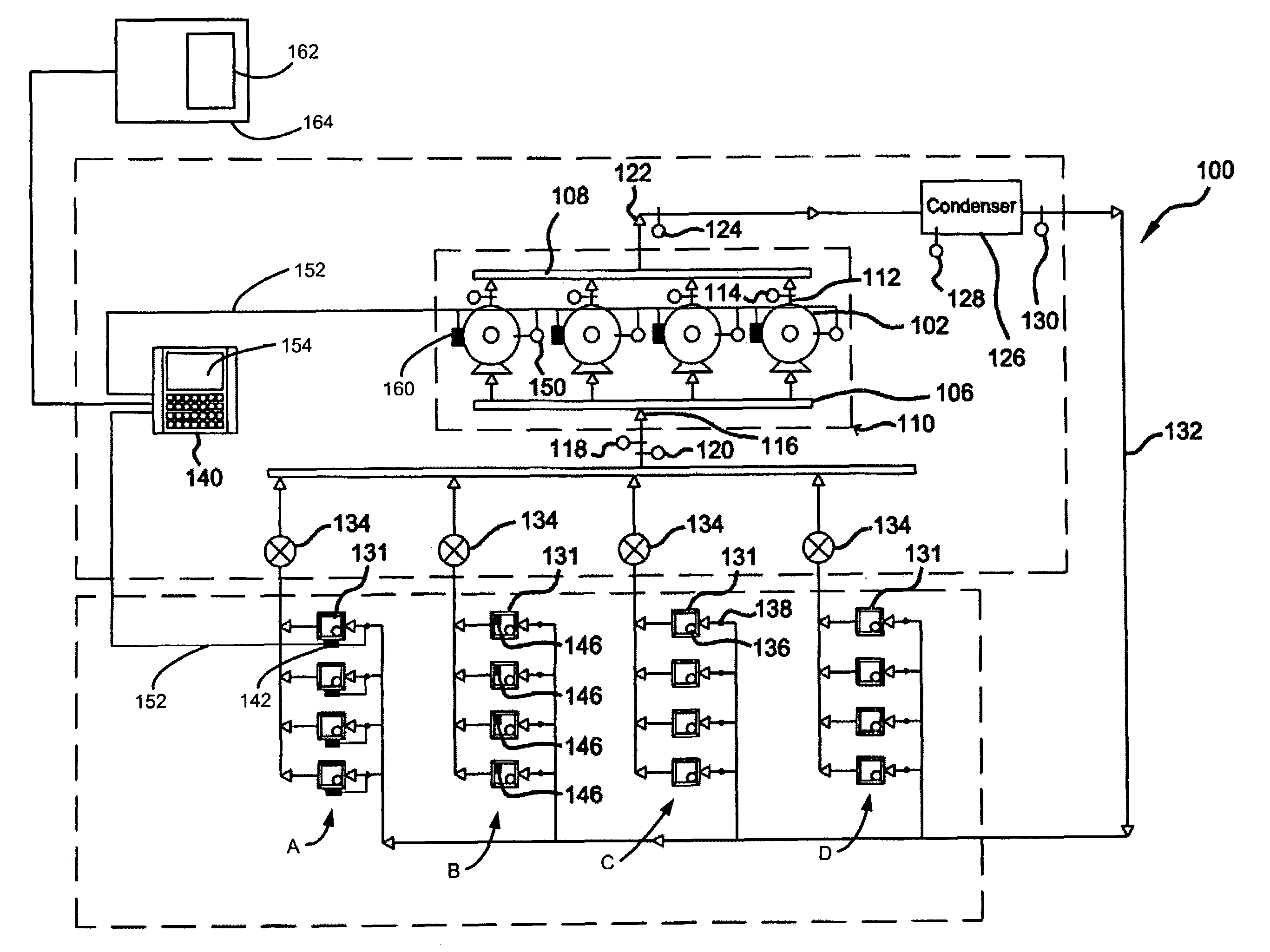
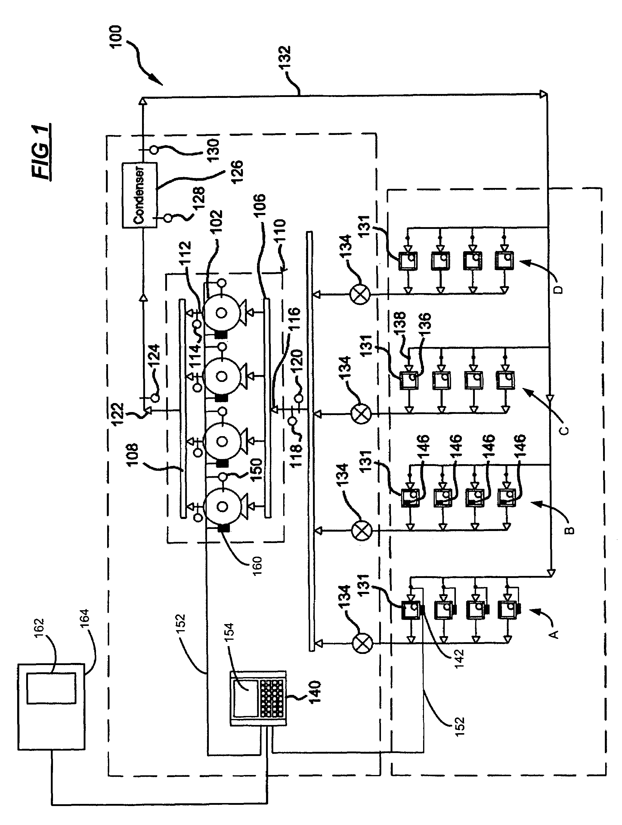
[0015]Referring now to FIG. 1, an exemplary refrigeration system 100 includes a plurality of refrigerated food storage cases 102. It will be appreciated that the hereindescribed refrigeration system 100 is merely exemplary in nature. The refrigeration system 100 may vary as particular design requirements dictate.

[0016]As shown, the refrigeration system 100 includes a plurality of compressors 102 piped together with a common suction manifold 106 and a discharge header 108 all positioned within a compressor rack 110. A discharge output 112 of each compressor 102 includes a respective temperature sensor 114. An input 116 to the suction manifold 106 includes both a pressure sensor 118 and a temperature sensor 120. Further, a discharge outlet 122 of the discharge header 108 includes an associated pressure sensor 124.

[0017]Th...


PUM

PropertyMeasurementUnit
voltageaaaaaaaaaa
currentaaaaaaaaaa
threshold numberaaaaaaaaaa

Abstract

A refrigeration system and method includes a refrigeration component and an electronics module preconfigured with a data set for the refrigeration component. The electronics module stores the data set including identification and configuration parameters of the refrigeration component. A refrigeration system controller that communicates with the electronics module to copy the data set and to regulate operation of the refrigeration component within the refrigeration system.

Description

CROSS-REFERENCE TO RELATED APPLICATIONS[0001]This application claims the benefit of U.S. Provisional Application No. 60 / 497,616, filed on Aug. 25, 2003, the disclosure of which is incorporated herein by reference.FIELD OF THE INVENTION[0002]The present invention relates to refrigeration control systems, and more particularly to integrated control and monitoring of refrigeration system compressors.BACKGROUND OF THE INVENTION[0003]Refrigeration systems typically include a compressor, a condenser, an expansion valve, and an evaporator, all interconnected to form a fluid circuit. Cooling is accomplished through evaporation of a liquid refrigerant under reduced temperature and pressure. Vapor refrigerant is compressed to increase its temperature and pressure. The vapor refrigerant is condensed in the condenser, lowering its temperature to induce a state change from vapor to liquid.[0004]The pressure of the liquid refrigerant is reduced through an expansion valve and the liquid refrigeran...

Claims


Application Information

Patent Timeline
Patent Type & Authority Patents(United States)
IPC IPC(8): G05D23/32F25B19/00F28D5/00G01K13/00F25B5/02F25B41/04F25B49/00F25B49/02
CPCF25B5/02F25B49/005F25B49/022F25B41/043F25B2400/075F25B2700/21161F25B2700/1931F25B2700/1933F25B2700/195F25B2700/21151F25B2700/21152F25B2400/22
Inventor WALLACE, JOHN G.ROHN, DAVID R.MAYNE, ALAN E.JAYANTH, NAGARAJRENKEN, TROY W.
Owner COPELAND COLD CHAIN LP
Why Eureka
Try Eureka