Wheel unit for ski-mounted vehicle

a technology for ski-mounted vehicles and wheels, which is applied in the direction of wheels, multiple wheel assemblies, transportation and packaging, etc., can solve the problems of being relatively difficult to steer, relatively fast subjected to excessive wear, and not well-suited to being driven across rougher surfaces, etc., to achieve easy retrofitability, easy installation, and mechanical simplicity

Inactive Publication Date: 2007-11-06
DESPRES JEAN
View PDF14 Cites 34 Cited by
  • Summary
  • Abstract
  • Description
  • Claims
  • Application Information

AI Technical Summary

Benefits of technology

[0012]Typically, the actuating plate defines a plate first surface and a plate second surface, the guiding slot extending through the piston attachment section of the actuating plate between the plate first and second surfaces; the piston-to-plate coupling means including a rod coupling block anchored to the piston rod, the rod coupling block defining a block abutment surface facing substantially towards the plate first surface, the rod coupling block extending substantially perpendicularly from the block abutment surface; the piston-to-plate coupling means also including a pin retaining component mounted on the rod coupling pin in an outwardly spaced relationship relative to the block abutment surface so as to define a circumferential plate receiving section on the rod coupling pin between the pin retaining component and the block abutment surface; the plate receiving section being inserted in the guiding slot with the block abutment surface and the pin retaining component positioned substantially adjacent respectively to the plate first and second surfaces for preventing the lateral withdrawing of the rod coupling pin from the guiding slot as the rod coupling pin slides along the guiding slot.
[0026]Yet, still furthermore, the proposed wheel unit is designed so as to provide a lateral movement of the wheel as the latter moves between its deployed and retracted configurations. More specifically, as the wheel is moved towards its deployed configuration, the wheel is displaced laterally outwardly so as to clear the ski and provide a relatively large sustentation base. Conversely, when the wheel is moved towards its retracted configuration, the wheel is simultaneously pulled radially inwardly so as to lessen the risk of the wheel causing obstruction in being subjected to impact by surrounding debris or objects.

Problems solved by technology

Although quite useful and efficient in their intended environment, conventional snowmobiles are not well-suited for being driven across rougher surfaces such as pavement, concrete, gravel or the like deprived of snow or ice.
When the skis of conventional snowmobiles are driven across such non-snow surfaces, they are relatively rapidly subjected to excessive wear.
Furthermore, when a conventional snowmobile is driven across a non-snow surface, it becomes relatively difficult to steer since the skis lose much of their usefulness.
However, the snowmobile wheel units shown in the prior art suffer from numerous drawbacks.
For example, some prior art wheel units are relatively complex and, hence, relatively expensive.
Furthermore, such prior wheel units often suffer from being mechanical failure and, as such, are considered unreliable.
Furthermore, some prior art wheel units suffer from being unprotected against relatively commonly encountered obstacles and are, hence, subject to being damaged during use of the snowmobile.

Method used


Image

  • Wheel unit for ski-mounted vehicle
  • Wheel unit for ski-mounted vehicle
  • Wheel unit for ski-mounted vehicle

Examples


Embodiment Construction

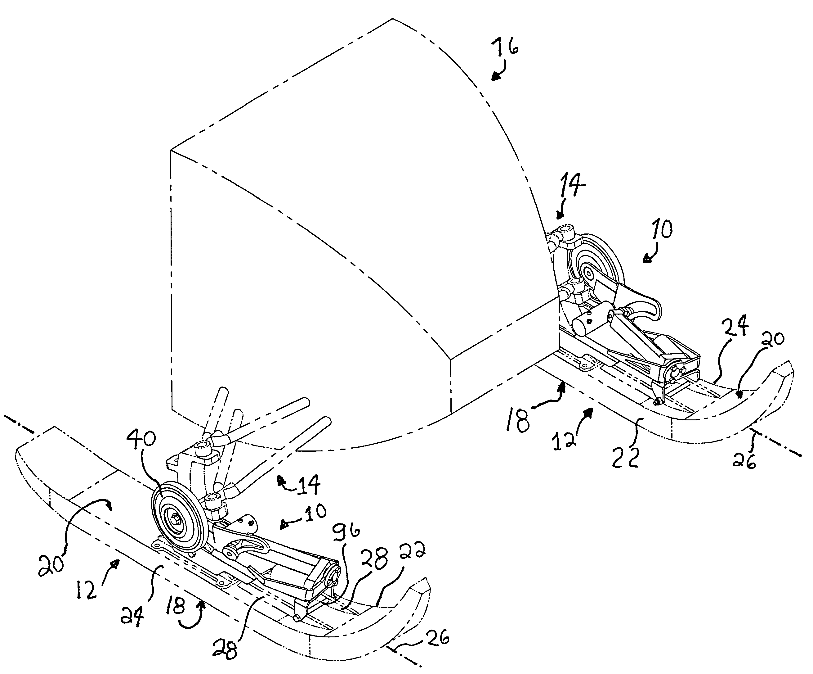
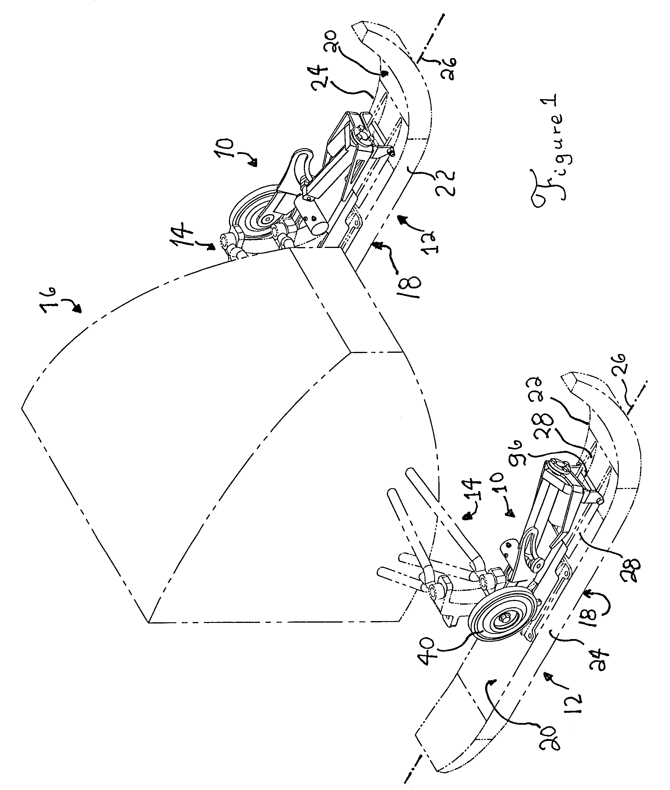
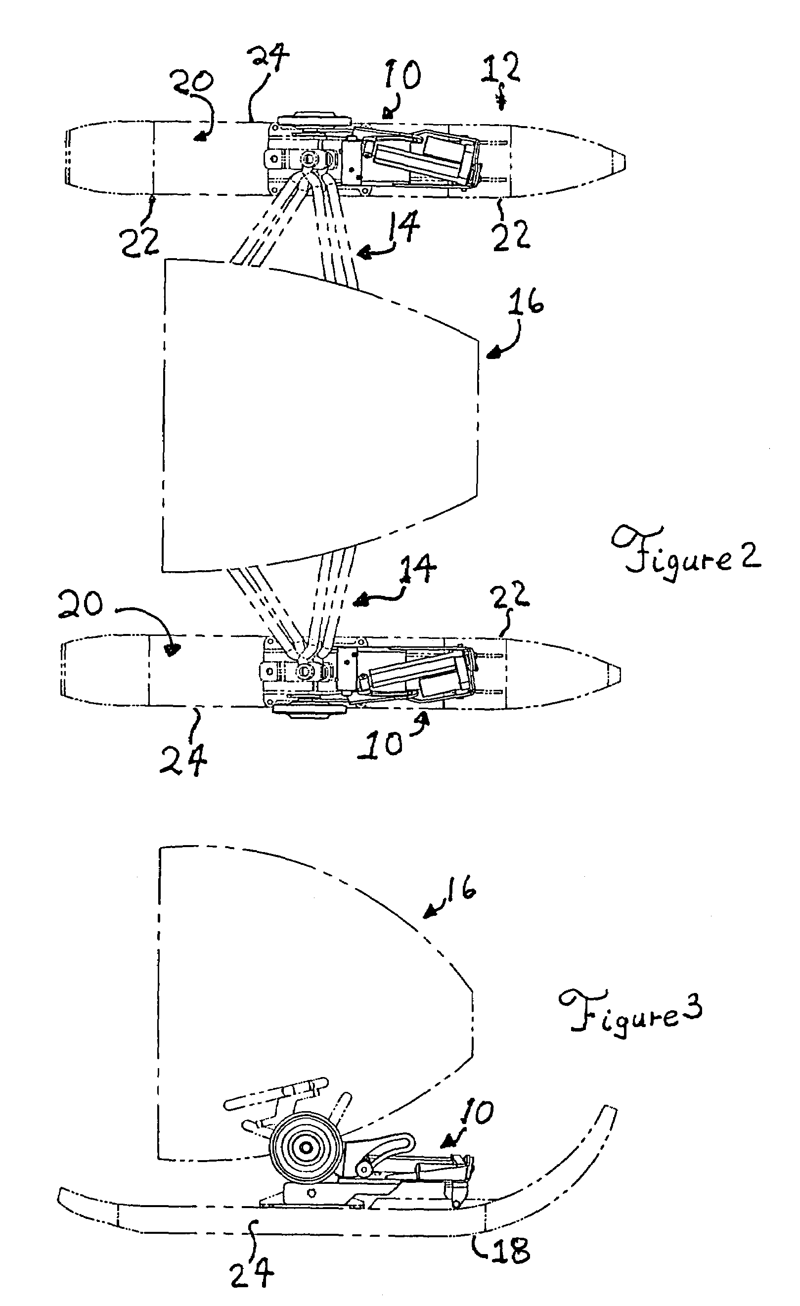
[0043]Referring to FIG. 1, there is shown a pair of wheel units, in accordance with an embodiment of the present invention, each generally indicated by the reference numeral 10. Each wheel unit 10 is shown mounted on a corresponding ski generally indicated by the reference numeral 12. Each ski 12 is attached by a suitable ski-to-vehicle attachment assembly 14 to a vehicle such as a snowmobile or other ski-mounted vehicle schematically represented and referred to by the reference numeral 16.

[0044]It should be understood that the wheel units 10 could be used with any suitable type of ski-mounted vehicle and with various types of skis without departing from the scope of the present invention. The skis 12 and the schematically represented vehicle 16 are only shown by way of example.

[0045]Each ski 12 typically has a ski gliding surface 18 for travelling over a suitable ground surface. Each ski 12 typically also has a substantially opposed ski upper surface 20, a ski inner side surface 22...


PUM


Abstract

A wheel unit mountable on a ski of a ski-mounted vehicle includes an actuating plate defining a wheel attachment section and a piston attachment section The actuating plate is pivotally attached to the ski intermediate the wheel and piston attachment sections for pivotal movement about a plate pivotal axis. A wheel attachment assembly is provided for rotatably attaching the wheel to the wheel attachment section. An actuator is operatively coupled to the actuating plate for selectively pivoting the actuating plate about the plate pivotal axis between a plate deployed configuration and a plate retracted configuration wherein in the plate deployed configuration the position of the actuating plate is such that the wheel protrudes at least partially below the ski gliding surface for engaging the ground surface and in the plate retracted configuration the position of the actuating plate is such that the wheel is retracted above the ski gliding surface for preventing the wheel from engaging the ground surface. A plate transversal moving assembly is operatively coupled to the actuating plate for selectively moving the actuating plate substantially transversally relative to the ski.

Description

FIELD OF THE INVENTION[0001]The present invention relates to the general field of ski-mounted vehicles such as snowmobiles and is particularly concerned with a wheel unit mountable on a ski of a ski-mounted vehicle.BACKGROUND OF THE INVENTION[0002]Snowmobiles are designed to ride primarily upon snow or ice, and, to this end, are provided with a pair of skis pivotally mounted adjacent the fore end of the snowmobile for gliding across the surface of the snow or ice. An endless drive track is disposed typically medially and rearwardly under the body of the snowmobile and aft of the skis. Typically, the skis are provided with a runner made out of carbide or other suitable material that runs along at least a portion of the bottom surface of the ski to keep the snowmobile travelling along a track.[0003]Although quite useful and efficient in their intended environment, conventional snowmobiles are not well-suited for being driven across rougher surfaces such as pavement, concrete, gravel o...

Claims


Application Information

Patent Timeline
Patent Type & Authority Patents(United States)
IPC IPC(8): B62B17/06B62B13/18
CPCB62B13/18
Inventor DESPRES, JEAN
Owner DESPRES JEAN
Why Eureka
Try Eureka