
Cradle for steering assembly

a steering assembly and cradle technology, applied in the direction of hydrostatic steering gears, vehicle components, understructures, etc., can solve the problems of poor performance compared with modern steering systems, undesirable use of u-bolts to couple rack and pinion housings to frame rails, and many older vehicles with antiqued steering systems. , to achieve the effect of easy installation

Active Publication Date: 2007-11-06
FLAMING RIVER INDS
View PDF20 Cites 10 Cited by
  • Summary
  • Abstract
  • Description
  • Claims
  • Application Information

AI Technical Summary

Benefits of technology

"The present invention is a replacement steering assembly for a rear steer vehicle. It includes a cradle that supports a new steering system and is designed to isolate it from other vehicle components. The cradle is easy to install and does not require any permanent alterations to the vehicle. The technical effects of this invention include proper steering system support, improved isolation from vehicle suspension components, and easy installation."

Problems solved by technology

The steering systems on many older vehicles are of antiqued design and have poor performance compared with modern steering systems.
Using U-bolts to couple the rack and pinion housing to the frame rails is undesirable because the rack and pinion system becomes part of the vehicle suspension system, essentially becoming a cross member that extends between the frame rails.
Since the rack and pinion system is not engineered to be a suspension member, such use typically leads to poor performance and / or premature failure of the rack and pinion steering system.
Unfortunately, because vehicles designed with a steering box did not envision mounting of a cradle between the front suspension mounting supports, providing clearance for the rack and pinion system and the cradle supporting it is problematic.
Obviously, cutting / removal of a suspension member is a major disadvantage both from a performance perspective and from a vehicle resale position.
Again, this approach has major disadvantages in requiring permanent alteration of the vehicle suspension along with the difficulty and cost attendant with drilling holes in or welding the suspension mounting supports.

Method used


Image

  • Cradle for steering assembly
  • Cradle for steering assembly
  • Cradle for steering assembly

Examples


Embodiment Construction

First Preferred Embodiment—Rear-Loaded Cradle

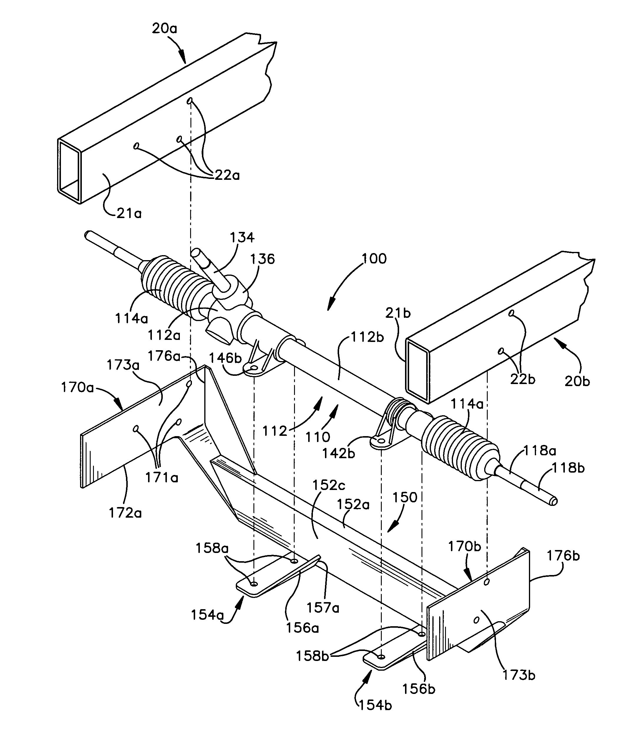
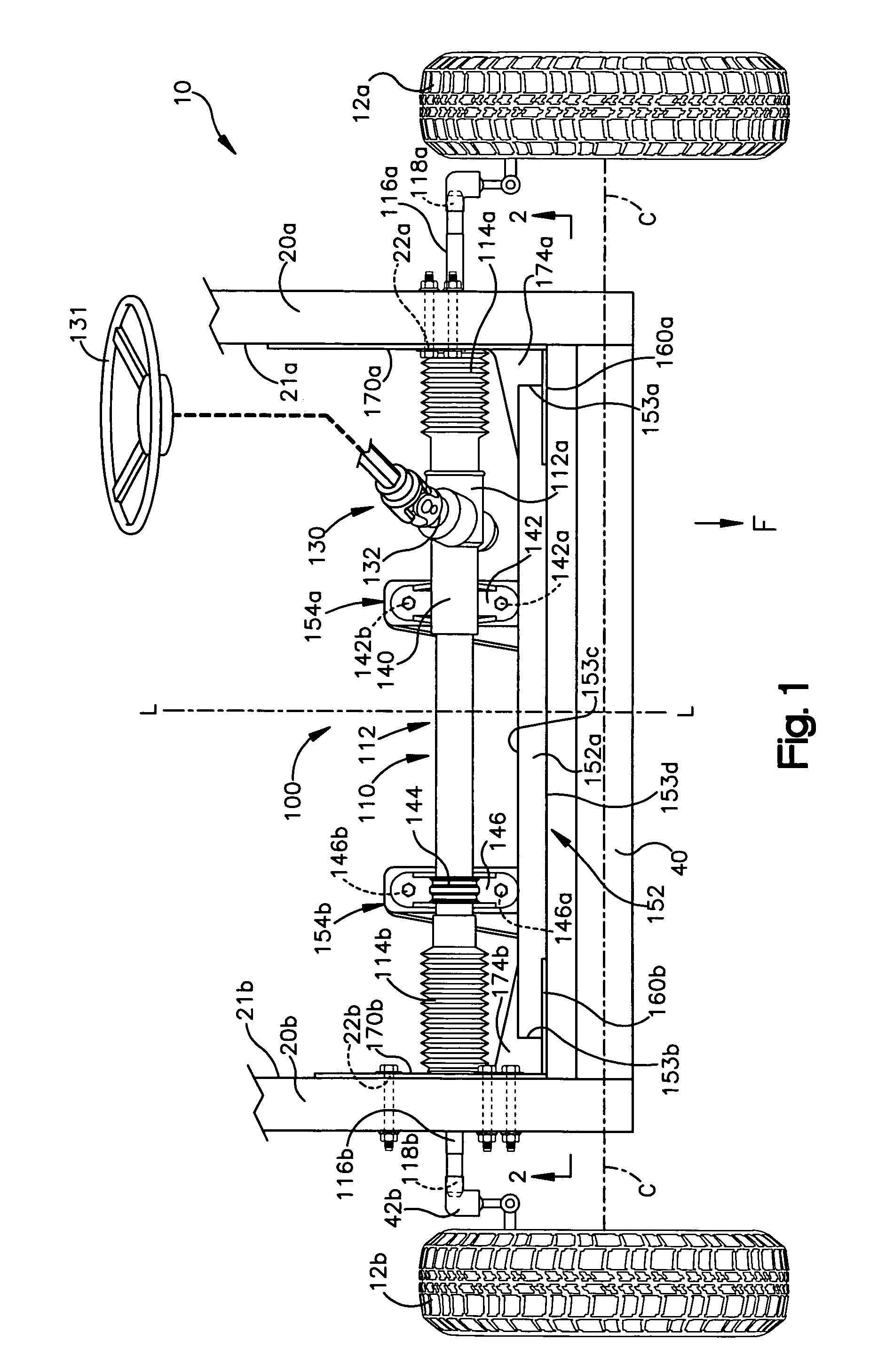
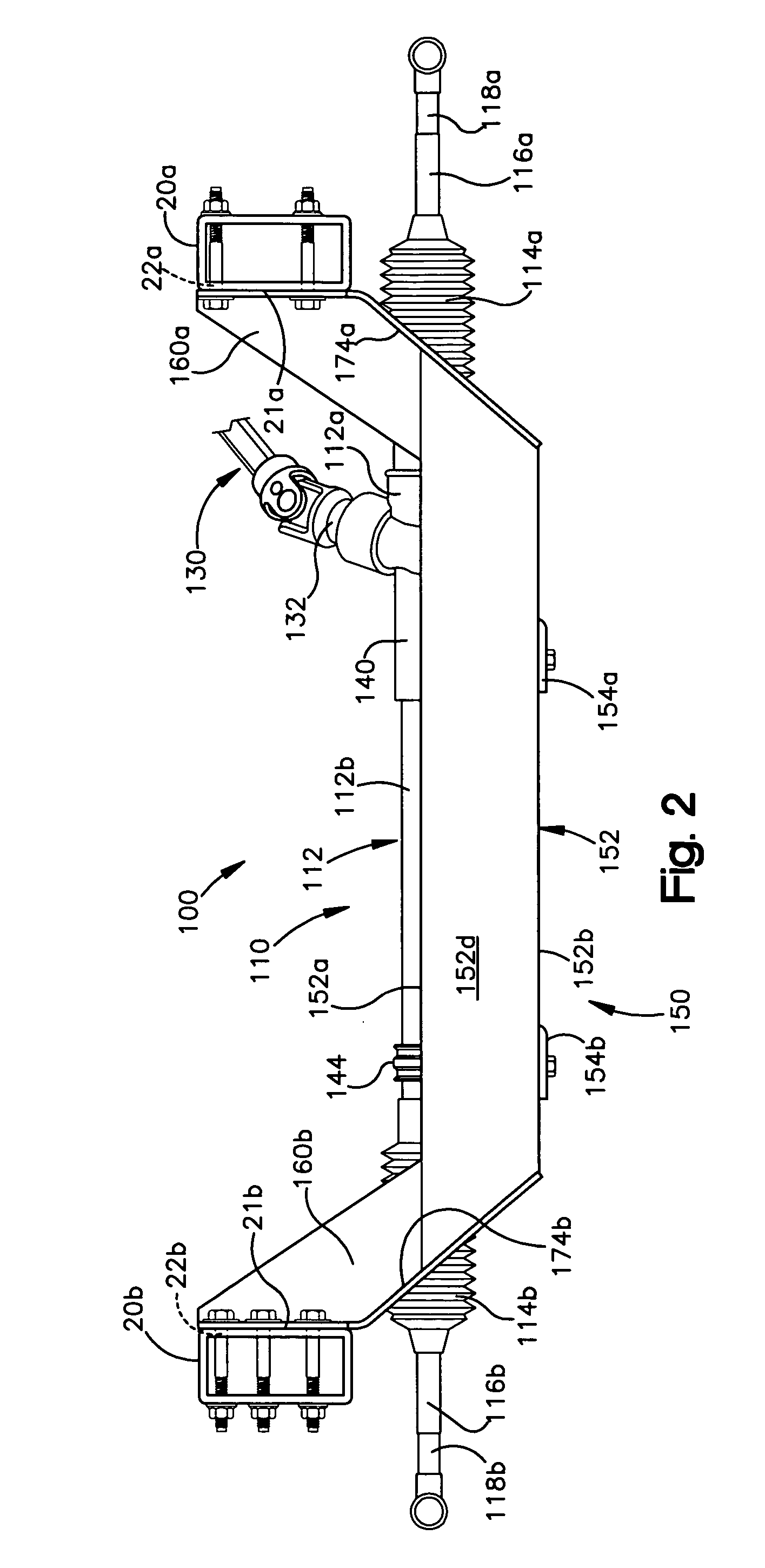
[0027]One preferred embodiment of a replacement steering assembly is shown at 100 in FIGS. 1-3. The replacement steering assembly 100 includes a manual rack and pinion steering system 110 supported by a cradle or support 150. Advantageously, the replacement steering assembly 100 may be used to replace the original OEM (original equipment manufacture) steering assembly of a vehicle 10 having a rear steer steering system (often referred as an Omni-type steering system) without the necessity of removing or cutting any vehicle suspension members or otherwise changing the chassis configuration.

[0028]The replacement steering assembly 100 of the present invention advantageously is a bolt-on system which extends between and bolts directly to the vehicle frame rails 20a, 20b. Moreover, since no cutting of suspension members is necessary and no welding of the cradle 150 to the frame rails 20a, 20b occurs, the replacement steering assembly 100 may b...


PUM


Abstract

The present invention is directed to a replacement steering assembly for a rear steer vehicle and requires no cutting / removal of suspension components or drilling holes or welding of vehicle frame rails. The replacement steering assembly includes a cradle for support a replacement steering system. The cradle includes spaced apart first and second side plates and a center support extending therebetween. A mounting portion of the first side plate includes mounting holes to affix the plate to the left side frame rail and a mounting portion of the second side plate includes mounting holes to affix the plate to the right side frame rail. The first and second side plate mounting holes are configured to align with existing mounting holes in the frame rails which were provided to mount original vehicle steering assembly. The center support is offset vertically downwardly and positioned forwardly of the side plate mounting portions.

Description

FIELD OF THE INVENTION[0001]The present invention relates to a replacement or aftermarket steering assembly and, more particularly, to a replacement steering assembly including a cradle for supporting the replacement steering system wherein the cradle is adapted to be directly bolted to the vehicle's frame rails without the need for welding or drilling the frame rails or cutting or removal of any vehicle suspension members.BACKGROUND OF THE INVENTION [0002]The steering systems on many older vehicles are of antiqued design and have poor performance compared with modern steering systems. Owners of such older vehicles, seeking to improve steering performance, may replace original equipment steering systems, such as steering boxes, with better performing, more reliable systems such as rack and pinion steering systems.[0003]When replacing a steering box with a rack and pinion steering system, the vehicle must support the rack and pinion system which typically extends between the vehicle'...

Claims


Application Information

Patent Timeline
Patent Type & Authority Patents(United States)
IPC IPC(8): B62D3/14
CPCB62D21/11B62D21/02
Inventor DOMIN, RONALD J.
Owner FLAMING RIVER INDS
Learn More