

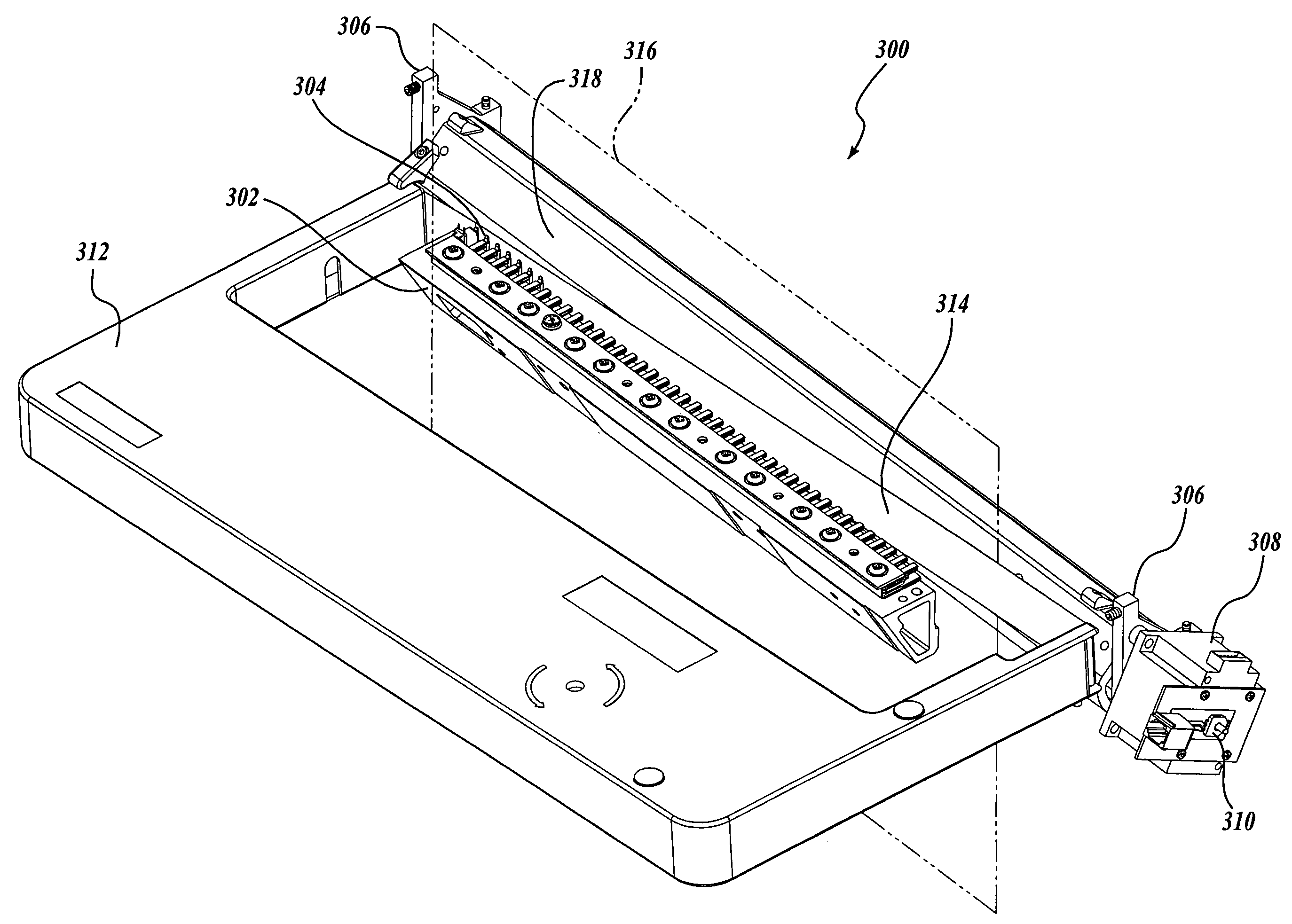
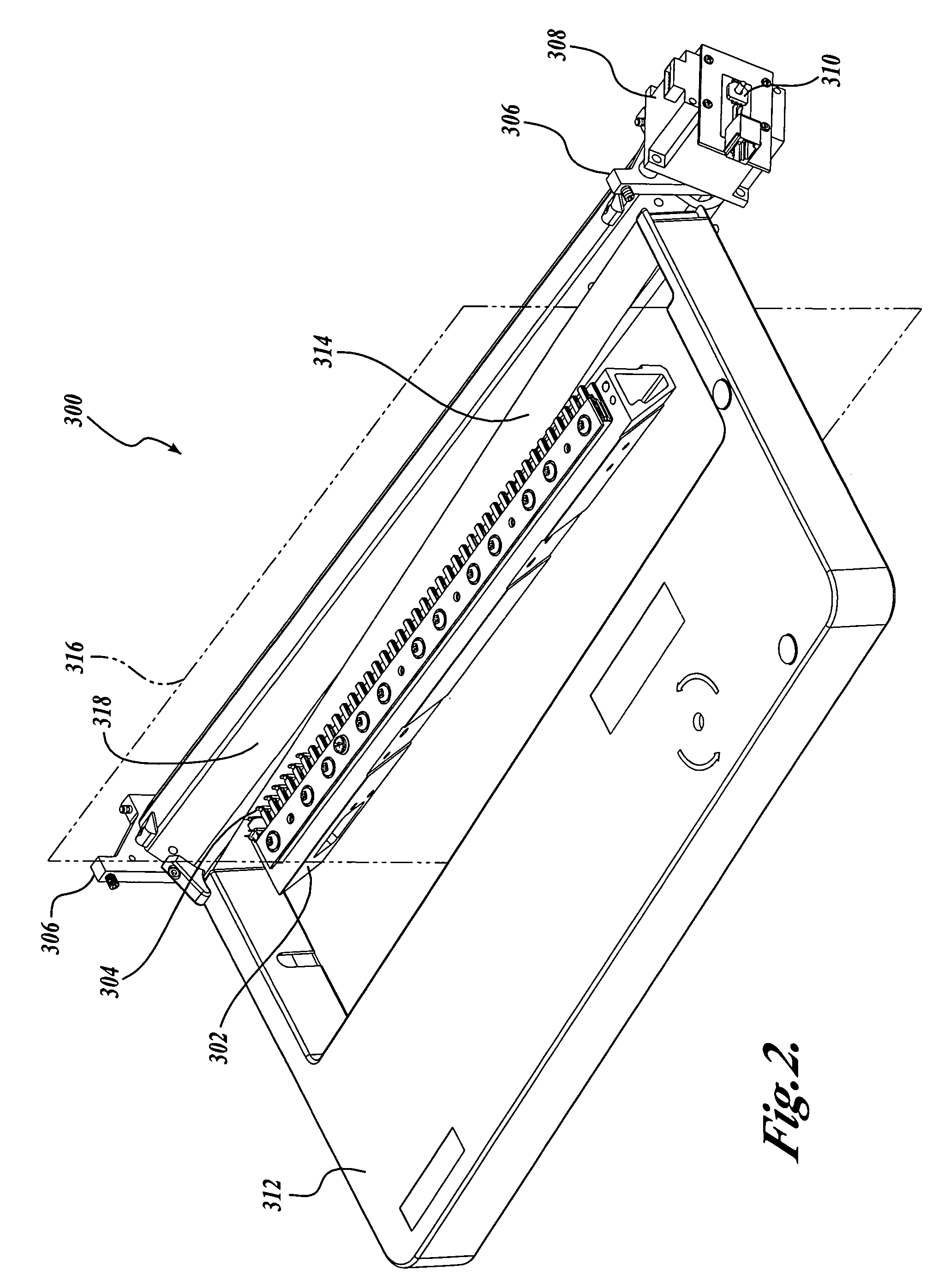
Line printer having a motorized platen that automatically adjusts to accommodate print forms of varying thickness
a technology of automatic adjustment and print form, which is applied in the direction of printing mechanism, printing, printing, etc., can solve the problems of smudging ink on the thick light printing on the thin portion of the form, etc., and achieve the effect of high print quality
- Summary
- Abstract
- Description
- Claims
- Application Information
AI Technical Summary
Benefits of technology
Problems solved by technology
Method used
Image

Examples
Embodiment Construction
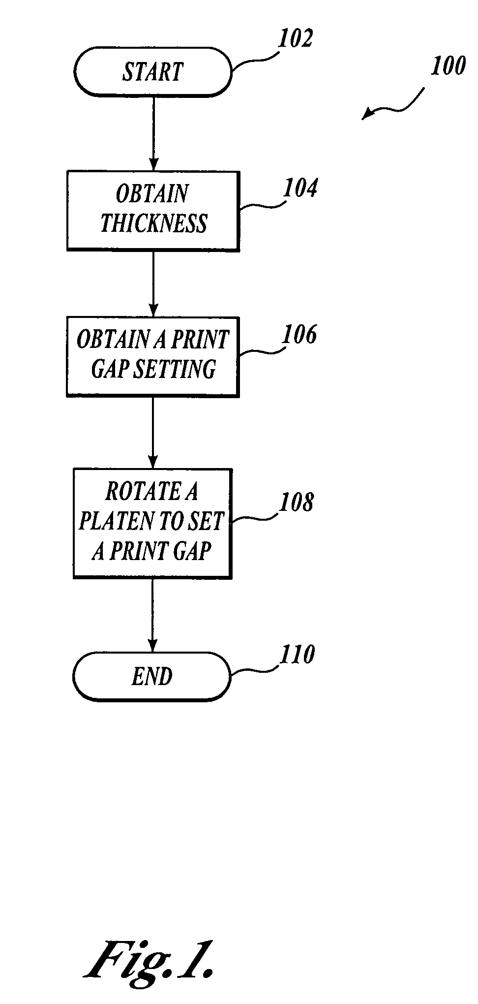
[0034]A method for setting the print gap distance by rotational change of an eccentric platen is described. A stepper motor can be used to rotate the eccentric platen. The stepper motor may have a rotary potentiometer or similar sensor attached to the motor shaft. The sensor may be used to verify that the platen has arrived at the commanded position. An eccentric platen, a stepper motor, and a sensor may be used to determine printing medium thickness before setting the print gap. Thickness is determined by applying a force against the printing medium with the eccentric platen, and recording the position of the platen. If the position of the platen is known, and the print gap distance is known as a function of the platen position, and the optimal print gap distance is known for a given paper thickness, the appropriate print gap distance may be set automatically. The optimal print gap may vary based on a number of factors, such as printer type, printing medium type, and the thickness ...
PUM
 Abstract
Description
Claims
Application Information