
IC socket

a socket and socket technology, applied in the direction of coupling device connection, electrical apparatus construction details, engagement/disengagement of coupling parts, etc., can solve the problems of buckling or deformation, ic package will not be accurately placed in a predetermined position, and it is difficult to correct the incorrect mounting state, so as to prevent buckling and deformation of contacts, good mounting workability

Inactive Publication Date: 2007-11-06
TYCO ELECTRONICS JAPAN GK
View PDF15 Cites 19 Cited by
  • Summary
  • Abstract
  • Description
  • Claims
  • Application Information

AI Technical Summary

Benefits of technology

[0007]The present invention has been developed in view of the foregoing circumstances. It is an object of the present invention to provide an IC socket which is capable of guiding an IC package to the proper position therefore on a mounting surface with good mounting workability, while preventing buckling and deformation of contacts.
[0008]It is another object of the present invention to provide an IC socket in which a guide member is stably urged upward, without increasing the number of parts.

Problems solved by technology

Therefore, there is a possibility that a corner of an IC package will strike the contacts of the IC socket, causing them to buckle or become deformed, if the IC package is dropped during mounting onto the IC socket or the like.
In addition, there is a possibility that the IC package will not be accurately placed in a predetermined position, and will be mounted in an inclined manner.
However, in the case that the IC package is mounted in an inclined manner, it is difficult to correct the incorrect mounting state thereof.
In the case that connections are established while the IC package is mounted in an inclined manner, there is a possibility that pins of the IC package will become deformed.

Method used


Image

  • IC socket
  • IC socket
  • IC socket

Examples


Embodiment Construction

)

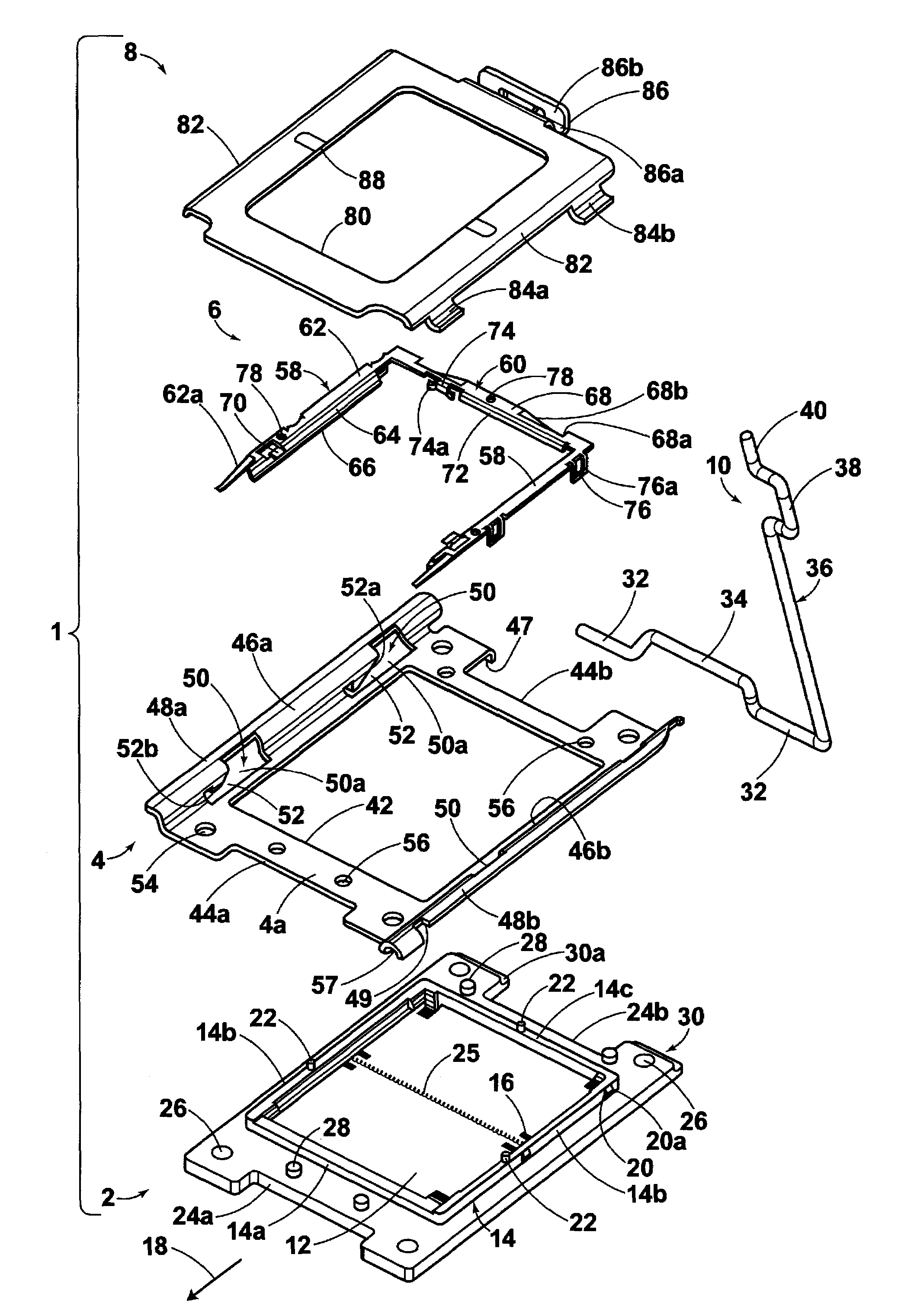
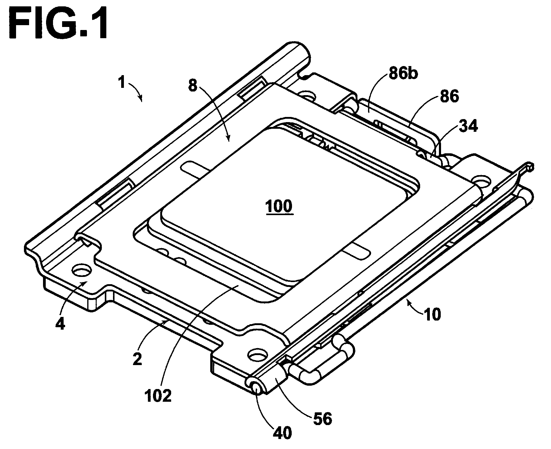
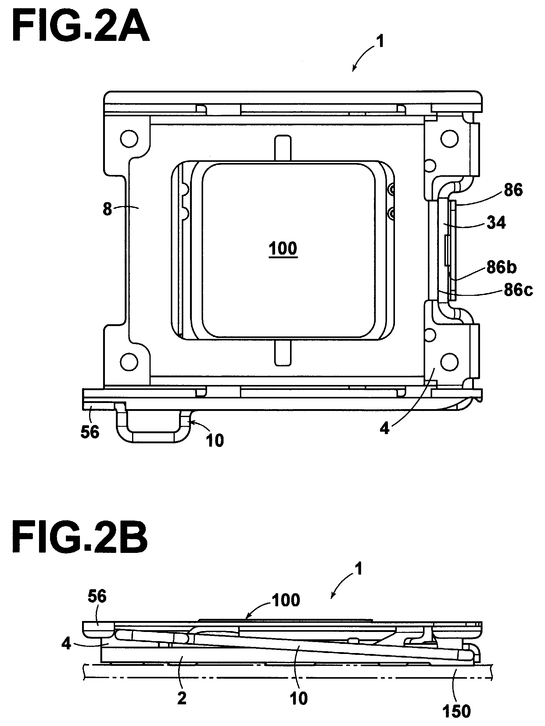
[0018]Hereinafter, a preferred embodiment of the IC socket of the present invention will be described in detail with reference to the attached drawings. FIG. 1, FIG. 2A and FIG. 2B illustrate an IC socket 1 of the present invention with an IC package 100 mounted thereon. The IC socket 1 comprises: a socket housing 2 (hereinafter, simply referred to as “housing”), which is to be mounted on a printed circuit board 150 (hereinafter, simply referred to as “circuit board”, refer to FIG. 2B); a metallic reinforcing member 4, which is attached to the housing 2; a guide member 6 (refer to FIG. 3), which is attached to the housing 2; a cover plate 8, for pressing the IC package 100, such as a CPU, which is placed on the housing 2; and a lever 10, for driving the cover plate 8. The IC socket 1 illustrated in FIG. 1, FIG. 2A and FIG. 2B has the LGA (Land Grid Array) type IC package 100 completely mounted thereon. That is, FIG. 1, FIG. 2A and FIG. 2B illustrate a state in which an electrical c...


PUM


Abstract

An IC package is guided to the proper position therefore on a mounting surface of an IC socket with good mounting workability, while preventing buckling and deformation of contacts. In addition, a guide member is enabled to be urged upward stably, without increasing the number of parts. The IC socket includes: an insulative housing that holds a plurality of contacts; a cover plate; and a lever. A guide member, which includes: a pair of guide rails for guiding the IC package; and a link member for linking the guide rails to each other, is attached to the housing. Spring arms for urging the guide member upward are provided on the guide rails and the link member. Regulating members that regulate upward movement of the guide member at a position, where the guided IC package does not contact the electrical contacts, are provided on the housing and the guide member.

Description

RELATED APPLICATION DATA[0001]This is a continuation application of U.S. Ser. No. 11 / 165,374, filed Jun. 23, 2005 now abandoned.FIELD OF THE INVENTION[0002]The present invention relates to an IC socket and more particularly, to an IC socket that has a guide member for use during insertion of an IC package.BACKGROUND OF THE INVENTION[0003]A first example of a known conventional IC socket, is disclosed in Japanese Unexamined Patent Publication No. 6(1994)-151025 (FIG. 1, FIG. 3). This IC socket comprises a housing that holds a large number of contacts and has an IC package positioning base and a rotatable cover plate for pressing an IC package against the positioning base.[0004]A second example of a known IC socket, is disclosed in Japanese Unexamined Patent Publication No. 5(1993)-174924 (FIG. 1, FIG. 3). This IC socket comprises a housing that holds a large number of contacts and has a PGA (Pin Grid Array) type IC package positioning base.[0005]In the first known IC socket, the top ...

Claims


Application Information

Patent Timeline
Patent Type & Authority Patents(United States)
IPC IPC(8): H01R13/62H01R33/76H05K7/10
CPCH05K7/1053
Inventor TODA, SHINSAKUKAJINUMA, SHUJIINOUE, MASASHI
Owner TYCO ELECTRONICS JAPAN GK
Learn More