Actuator including intermediate wall

a technology of actuators and intermediate walls, applied in the field of actuators, can solve the problems of deterioration of circuits and impairment of the performance of structural components of the drive mechanism portion, and achieve the effects of reducing the size of the actuator, improving durability, and not affecting performan

Active Publication Date: 2007-11-06
KOITO MFG CO LTD
View PDF18 Cites 26 Cited by
  • Summary
  • Abstract
  • Description
  • Claims
  • Application Information

AI Technical Summary

Benefits of technology

[0011]Accordingly, with the actuator of the present invention, grease, oil, and the like, that is used for the drive mechanism portion is blocked by the intermediate wall and thus do not adhere to a board of the control circuit portion. Moreover, cutting debris of the board of the control circuit portion is blocked by the intermediate wall, and thus does not get jammed in the gears of the drive mechanism portion. As a result, the electronic components on the board of the control circuit portion do not deteriorate due to grease, oil, and the like. Further, performance is not adversely affected by cutting debris of the board of the control circuit portion being jammed in the gears of the drive mechanism portion. Accordingly, desired performance can be fully demonstrated and durability improved.
[0012]In a further embodiment of the invention, the intermediate wall is formed so as to divide a space within the housing in the thickness direction of the control circuit use board. The drive mechanism portion is disposed in one side of the divided space, and the control circuit portion is disposed in the other side of the divided space. Accordingly, it is possible to reduce the size of the actuator in the horizontal plane.
[0013]In yet a further embodiment, a support shaft for the output shaft and / or for the transmission gear system is formed in the intermediate wall, and thus it is possible to reduce the number of components. Accordingly, cost reduction and production efficiency can both be improved.
[0014]In another embodiment, the intermediate wall is formed integrally with a side surface wall of the housing. As a result, stiffness of the housing is ensured, and positional accuracy improved.
[0015]In still a further embodiment, the motor is a brushless motor, and a magnetically sensitive element is provided on the control circuit use board so as to face an end surface of a rotor magnet of the motor through a hole formed in the intermediate wall. Accordingly, hardly any cutting debris is generated from the motor by rotation thereof, and it is possible to maintain the space on the drive mechanism portion side in a clean state.

Problems solved by technology

As a result, a problem has become apparent in that grease, oil, and the like, that are used in the drive mechanism portion adhere to electronic components on the board of the control circuit portion, thus causing deterioration of the circuit.
Moreover, other problems occur such as the performance of the structural components of the drive mechanism portion being impaired as a result of cutting debris of the board of the control circuit portion becoming jammed in the gears of the drive mechanism portion.

Method used


Image

  • Actuator including intermediate wall
  • Actuator including intermediate wall
  • Actuator including intermediate wall

Examples


Embodiment Construction

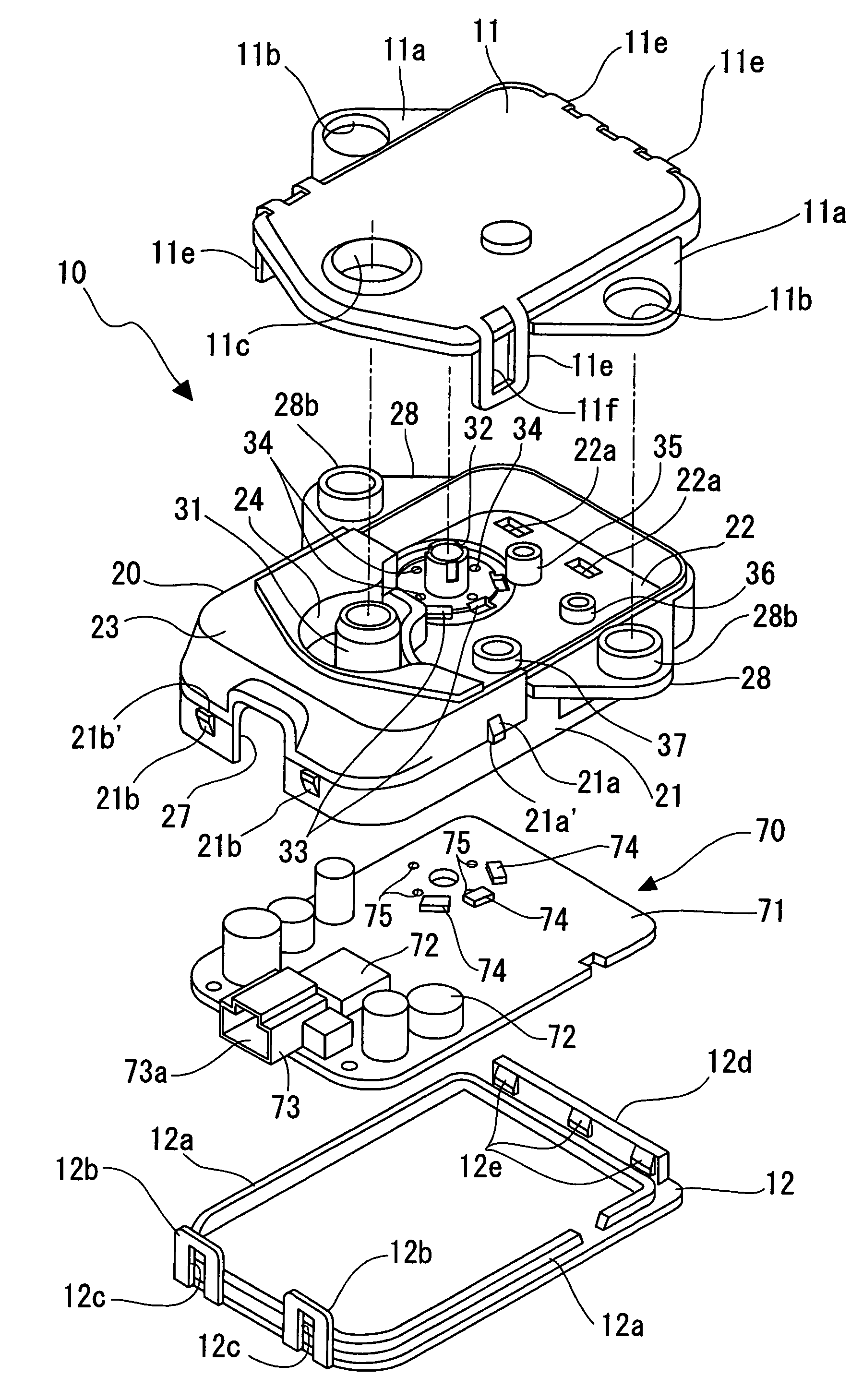
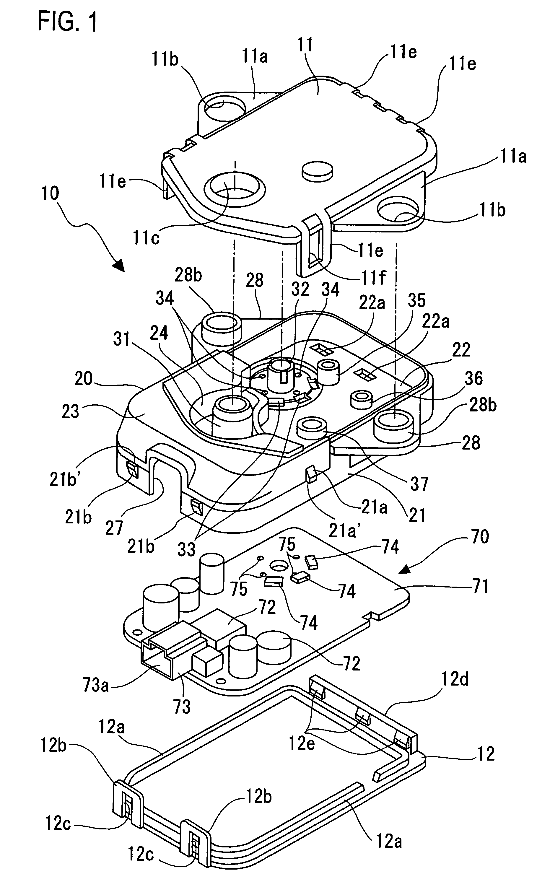
[0024]An actuator 1 includes: an oblong box-shaped housing 10 which is flat in the up-down direction and which is slightly longer toward the front and back; and necessary components and elements that are disposed therein.

[0025]As is apparent from FIG. 1, the housing 10 is formed from three portions, namely, a middle case 20, an upper cover 11, and a lower cover 12. These three portions 20, 11, and 12 are formed as synthetic resin molded components.

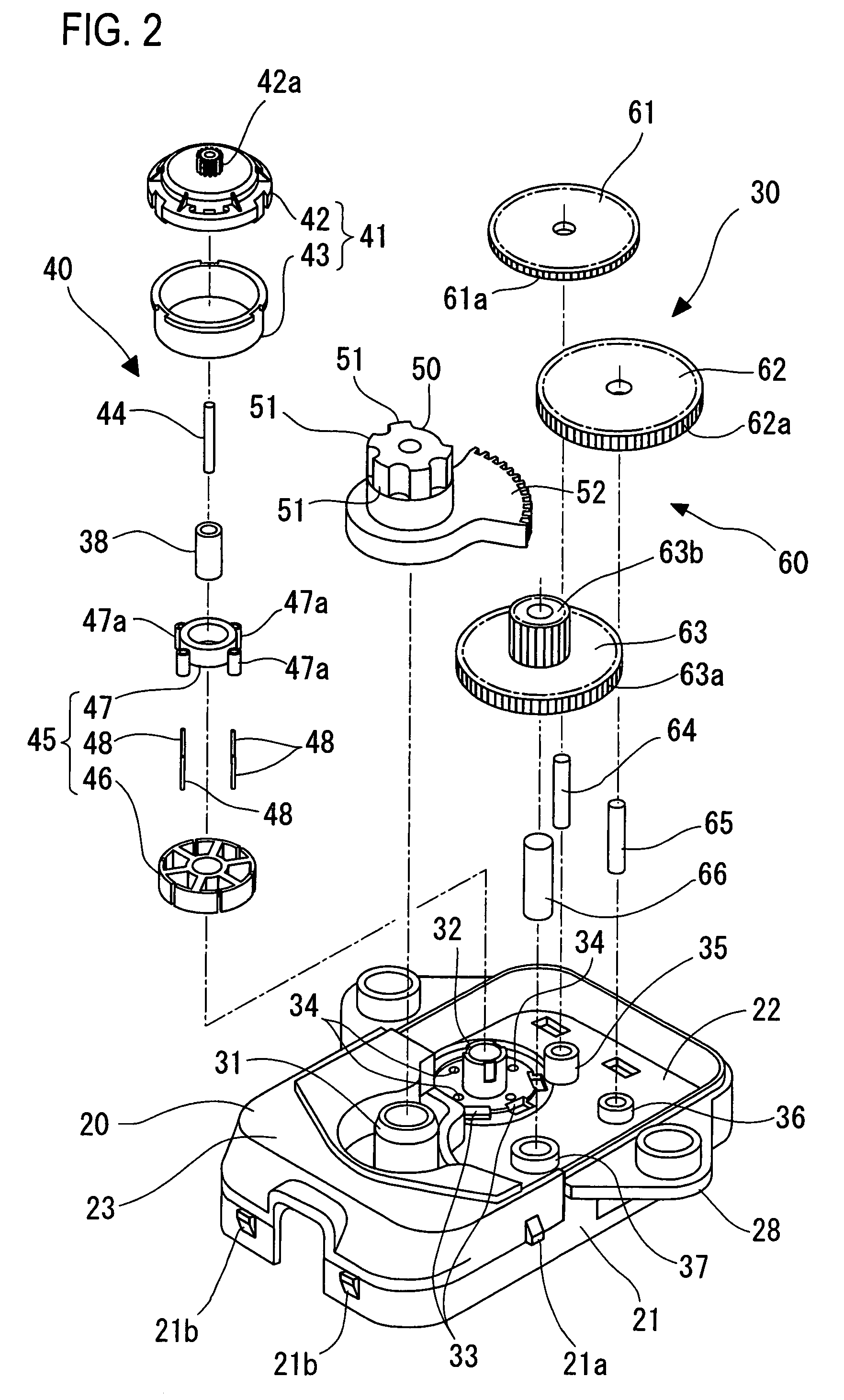
[0026]The middle case 20 includes a side surface wall 21 with some degree of up-down breadth. The inside area of the side wall surface 21, excluding a front end portion thereof, is divided in the up-down direction by an intermediate wall 22 having a peripheral edge that directly abuts with the internal surface of the side surface wall 21. If the intermediate wall 22 and the side surface wall 21 are viewed in cross section (refer to FIG. 5), they form an H-shape. Accordingly, the strength of the middle case 20, and by corollary, that of the...


PUM


Abstract

An actuator has a housing that accommodates a motor, an output shaft for rotating a lamp unit that radiates light, a drive mechanism portion formed from a transmission gear system for transmitting rotation from the motor to the output shaft, and a control circuit portion for controlling the drive of the motor, the drive mechanism portion and the control circuit portion being disposed in a separated state due to an intermediate wall.

Description

CROSS-REFERENCE[0001]This claims the benefit of Japanese Patent Application No. 2004-67084, filed Mar. 10, 2004, which is incorporated herein in its entirety.TECHNICAL FIELD[0002]The present invention relates to an actuator. More particularly, the present invention relates to a technology for improving durability of an actuator for rotating a lamp unit in order to change the direction of radiation of a vehicular lamp.BACKGROUND[0003]In a vehicle, for example, an automobile, the direction of radiation of a lamp is appropriately changed in accordance with the running conditions.[0004]For example, a structure that enables a head lamp unit to be rotated to the left and right directions and an actuator that rotates the lamp unit in the left and right directions may be provided, and when the automobile is turning, the direction of radiation of the lamp unit may be turned.[0005]Unexamined Japanese Patent Publication No. 2002-160581 proposes an actuator for driving a lamp unit in order to a...

Claims


Application Information

Patent Timeline
Patent Type & Authority Patents(United States)
IPC IPC(8): H02K7/10B60Q1/076H02K5/00B60Q1/12F21S8/10F21V14/00F21V21/02F21W101/10F21Y101/00
CPCB60Q1/076
Inventor TAKIGUCHI, TSUTOMUTAJIMA, KEIICHIMOCHIZUKI, KAZUMATAKII, NAOKI
Owner KOITO MFG CO LTD
Why Eureka
Try Eureka