Protection device for switches

a technology for protecting devices and switches, applied in the direction of protective switch details, protective switch terminals/connections, relays, etc., can solve the problems of affecting the deformation of bi-metallic plates, inaccurate arrangement of parts, and increase the cost of products, so as to reduce manufacturing costs and facilitate movement of links

Active Publication Date: 2007-11-06
YU TSUNG MOU
View PDF18 Cites 10 Cited by
  • Summary
  • Abstract
  • Description
  • Claims
  • Application Information

AI Technical Summary

Benefits of technology

[0005]The main object of the present invention is to provide a sufficient space for movement of the link so that when overloaded, the link is allowed to move into the extension slot to let the bi-metallic plate deform completely.
[0006]Another object of the present invention is to provide a safety switch wherein the bi-metallic plate is deformed completely when overloaded and does not bounce back to connect the two contact points so that accident sparks are completely avoided.
[0007]Yet another object of the present invention is to provide a safety switch that includes less number of parts so as to have lower manufacturing cost.

Problems solved by technology

There are too many parts involved in the safety switch device and a longer period of time is required when assembling the switch device, this increases the cost of the products.
The parts might be arranged inaccurately and would affect the deformation of the bi-metallic plate.

Method used


Image

  • Protection device for switches
  • Protection device for switches
  • Protection device for switches

Examples


Embodiment Construction

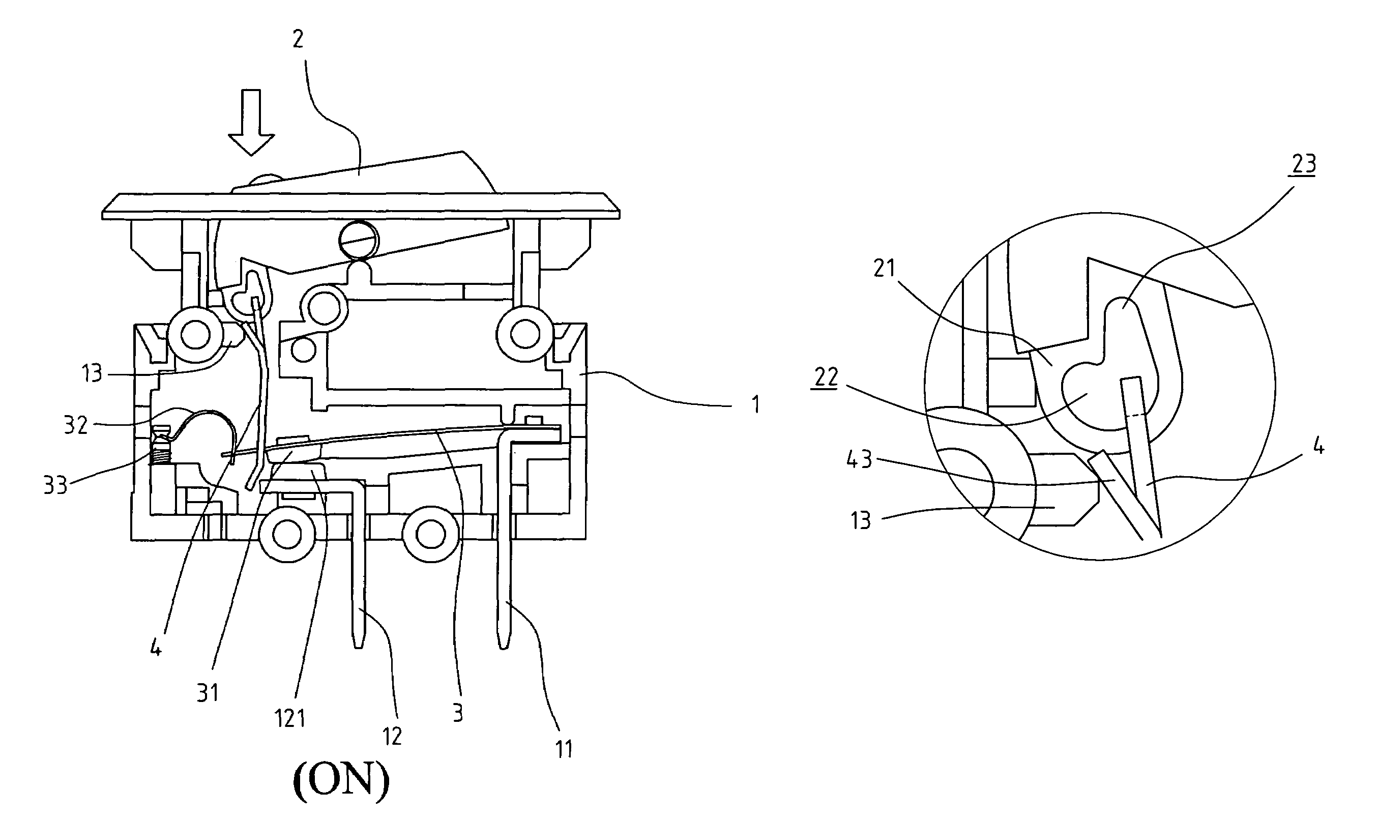
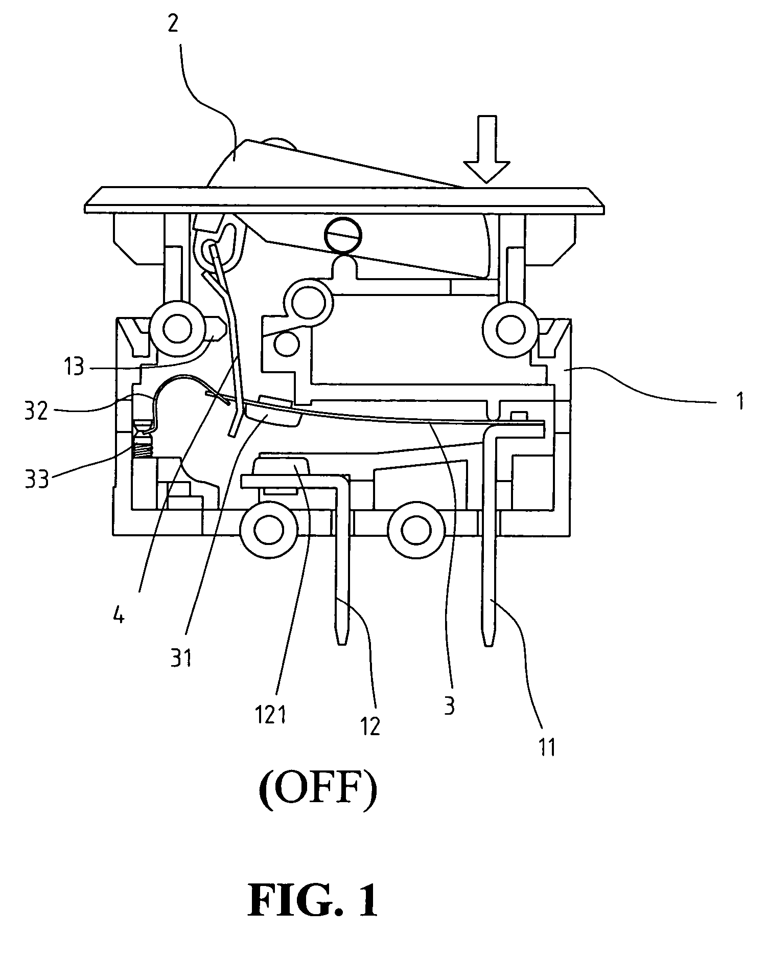
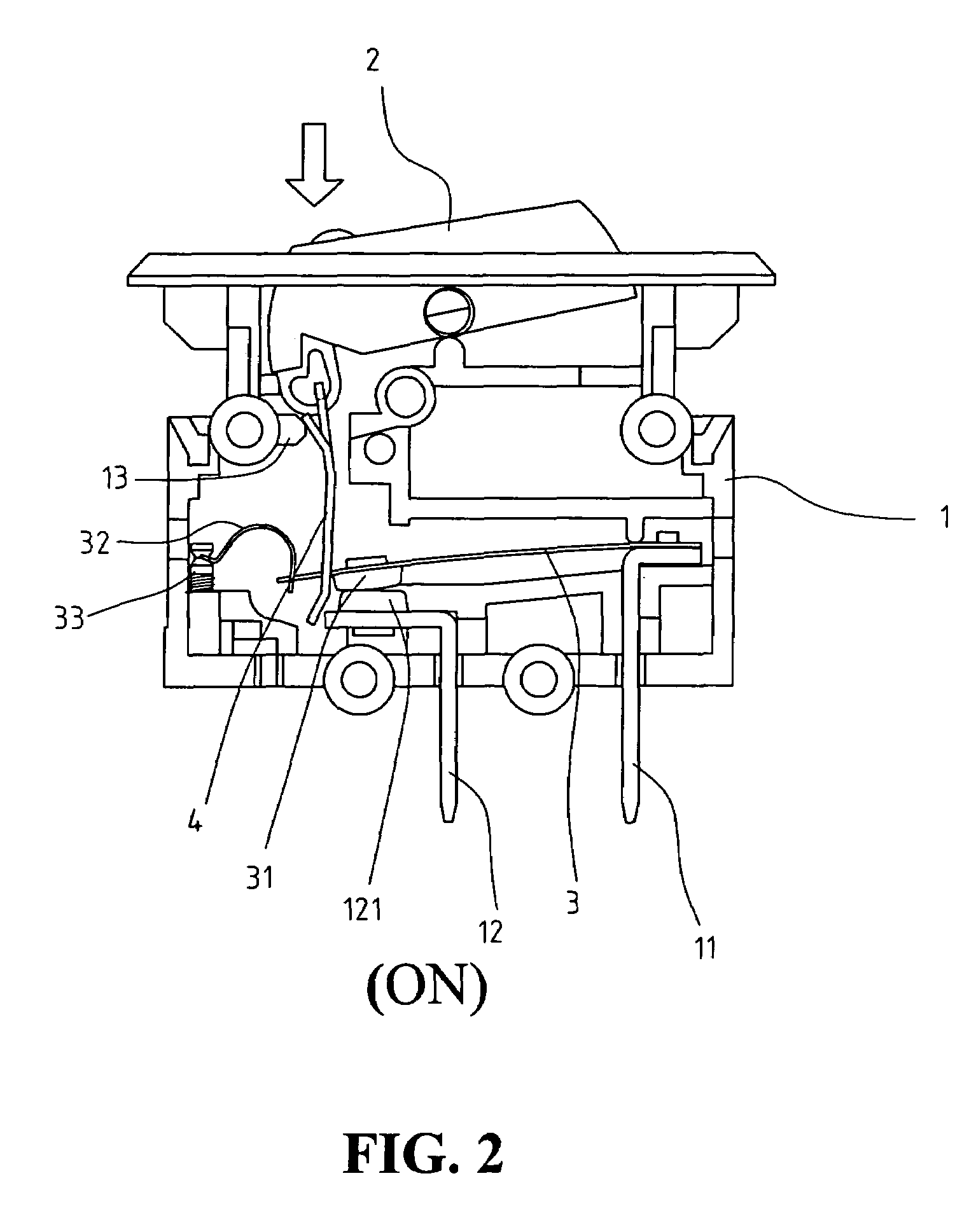
[0016]Referring to the drawings and in particular FIGS. 1, 2 and 4, a safety switch device of the present invention comprises a body 1 with a top opening and a switch member 2 is pivotably engaged with the top opening of the body 1 by a pin so that the switch member 2 can be pivoted about the pin. A first terminal 11 and a second terminal 12 extend through a bottom of the body 1. A contact portion 13 extends from an inside of the body 1. The switch member 2 has a protrusion 21 extending from an underside of an end thereof and an engaging hole 22 is defined in the protrusion 21. An extension slot 23 is in communication with the engaging hole 22.

[0017]A contact plate 3, which is a curve flexible bi-metallic plate, has a first end fixed to the first terminal 11 and a first contact point 31 connected to an underside of a second end of the contact plate 3. A second contact point 121 is located on the second terminal 12 and the first contact point 31 located above the second contact point...


PUM


Abstract

A switch device includes a body with a switch member pivotably engaged with a top opening of the body and a first terminal and a second terminal respectively extend through a bottom of the body. A bi-metallic plate has a first end fixed to the first terminal and includes a first contact point which is located above a second contact point on the second terminal. A link has an upper end pivotably connected with a protrusion on an underside of the switch member and a lower end of the link clamps the second end of the bimetallic plate. The protrusion includes an engaging hole and an extension slot is in communication with the engaging hole. The upper end of the link has a biasing plate which contacts a contact portion in the body so as to provide a potential force to keep the link upright. When overloaded, the bi-metallic plate is deformed upward and the upper end of the link is moved into the extension slot to ensure that the bi-metallic plate is deformed completely.

Description

FIELD OF THE INVENTION[0001]The present invention relates to a protection device for a safety switch to ensure the bi-metallic plate to be deformed as desired when overloaded.BACKGROUND OF THE INVENTION[0002]A conventional switch device, especially from those switches using bimetallic plate to prevent from being burn when an overload is happened, generally includes a bi-metallic plate which is deformed when overloaded so as to separate the two contact points respectively located on the bimetallic plate and one of the two terminals. U.S. Pat. Nos. 5,262,748; 4,167,720; 4,937,548; 5,223,813; 5,451,729; and 5,558,211 respectively disclose safety switches. Some inherent shortcomings for these conventional safety switch devices are found. There are too many parts involved in the safety switch device and a longer period of time is required when assembling the switch device, this increases the cost of the products. The parts might be arranged inaccurately and would affect the deformation o...

Claims


Application Information

Patent Timeline
Patent Type & Authority Patents(United States)
IPC IPC(8): H01H37/52H01H37/02H01H71/16H01H71/58
CPCH01H73/26
Inventor YU, TSUNG-MOU
Owner YU TSUNG MOU
Why Eureka
Try Eureka