Protective device for a liquid crystal display

a protective device and liquid crystal display technology, applied in the direction of instruments, machine supports, electrical apparatus casings/cabinets/drawers, etc., can solve the problems of high manufacturing cost of hanging protective glass, easy deterioration of adhesive or double-sided tape, etc., to eliminate the drawbacks

Inactive Publication Date: 2007-11-06
SHE WANG LUNG
View PDF6 Cites 23 Cited by
  • Summary
  • Abstract
  • Description
  • Claims
  • Application Information

AI Technical Summary

Benefits of technology

[0007]To overcome drawbacks of the conventional protective devices for the liquid crystal display, a novel protective device is provided to eliminate the drawbacks.
[0008]A main objective of the present invention is to provide a protective device for the liquid crystal display, wherein the protective device is conveniently attached to the liquid crystal display, completely protects the liquid crystal display and keeps the liquid crystal display neat in appearance.
[0009]Another main objective of the present invention is to provide a protective device for the liquid crystal display, wherein the protective device has a simple structure in a small size and does not cover adjusting buttons on the liquid crystal display.

Problems solved by technology

However, the panel of the liquid crystal display is soft and easily penetrated by sharp objects so that the panel needs a protective device.
When the hanging-type protective glass does not have securing devices attached below, the glass will swing easily, bump the panel and cause noise.
Moreover, the hanging-type protective glass has a high manufacturing cost and can not be modified easily because its structure is complex.
However, the adhesive or the double-sided tape easily deteriorates and then loses its adhesive capability so that the protective membrane can easily fall from the panel suddenly.
Therefore, the protective membrane is not durable.
Additionally, when the size of the protective membrane does not correspond to the screen of the panel, the protective membrane must attach to the screen directly and the adhesive will consequently stain the screen.

Method used


Image

  • Protective device for a liquid crystal display
  • Protective device for a liquid crystal display
  • Protective device for a liquid crystal display

Examples


Embodiment Construction

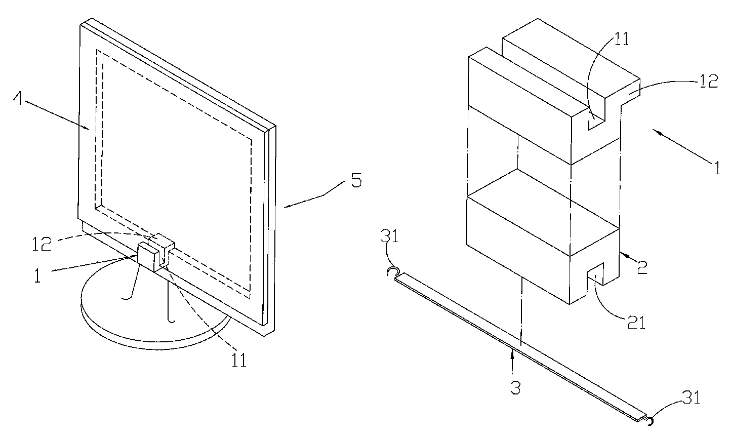
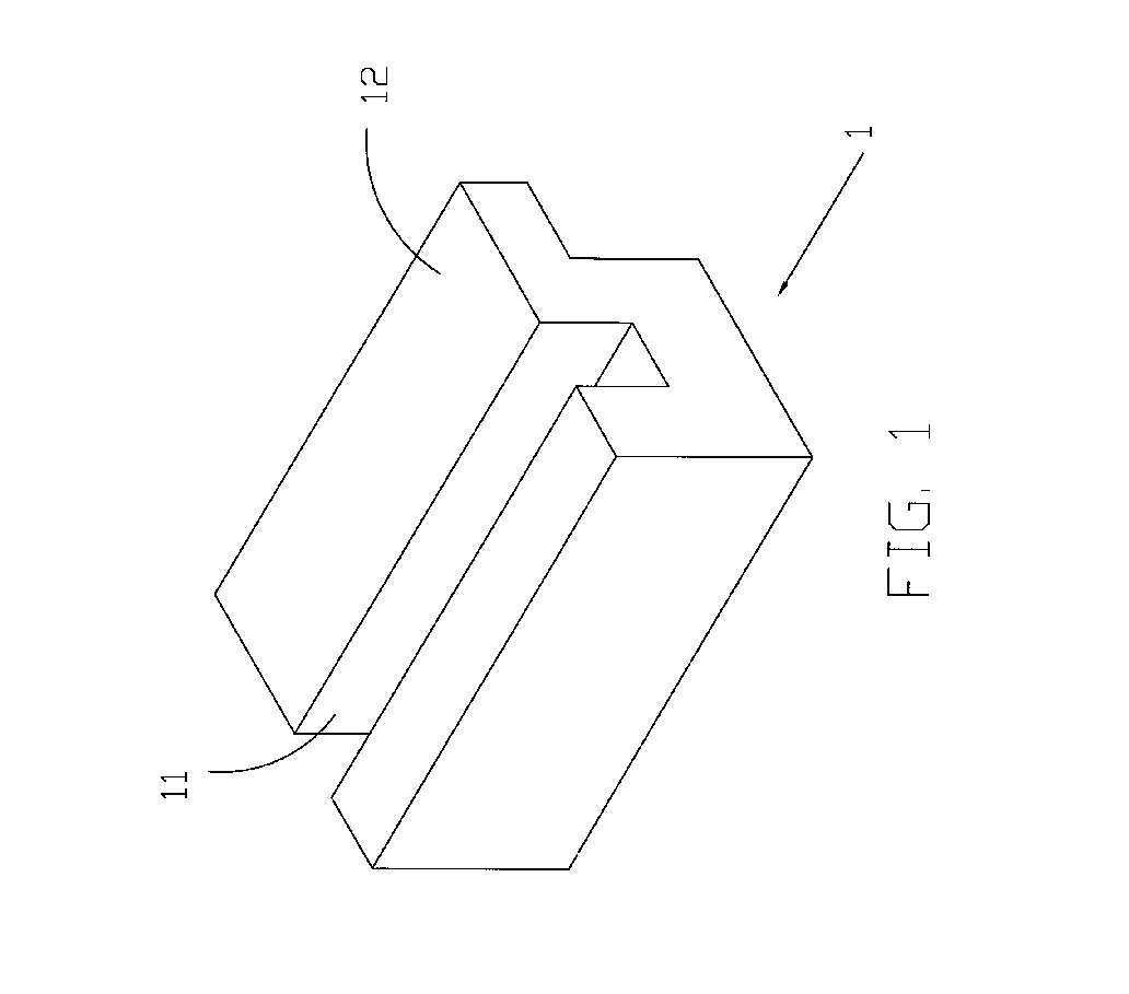
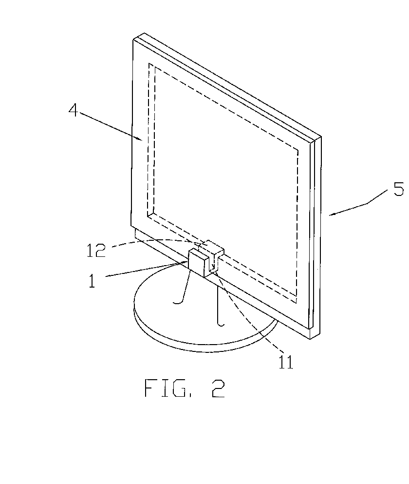
[0029]A protective device for a liquid crystal display in accordance with the present invention comprises a protective plate, a plate holder, a holding block, a strip and an optional clamping device. The plate holder has a U-shaped body with a groove on top, a flange extending toward the liquid crystal display, and an abutting recess defined under the flange. The holding block is attached to the plate holder and has a channel for receiving the strip. When the protective device mounts on a monitor of the liquid crystal display, the plate holder attaches to a joint of a screen panel and an outer frame of the monitor by resting the flange on the a flat top of the outer frame to make the abutting recess snugly combine with the outer frame. The protective plate engages the groove and erects in front of the screen panel of the monitor. Moreover, the strip further ties the protective plate on the monitor and the clamping device holds the protective plate and the outer frame of the monitor ...


PUM


Abstract

A protective device for a liquid crystal display has a protective plate, a plate holder, a holding block, a strip and a clamping device. The plate holder has a groove on a top, a flange extending backward and an abutting recess defined under the flange. The holding block combines with the plate holder and has a channel for receiving the strip. When the protective device mounts on a monitor of the liquid crystal display, the flange rests on a flat top of an outer frame of the monitor to make the abutting recess snugly combine with the outer frame. When the protective plate engages the groove and erects in front of a screen panel of the monitor, the strip ties the protective plate and the monitor together and the clamping device holds the plate and the outer frame of the monitor to keep the protective plate steady.

Description

BACKGROUND OF THE INVENTION[0001]1. Field of the Invention[0002]The present invention relates to a protective device for a liquid crystal display and, more particularly, to a protective device that can be conveniently attached to a liquid crystal display, has a simple structure and keeps the appearance of the liquid crystal display neat to view the full screen on the liquid crystal display without obstruction.[0003]2. Description of Related Art[0004]A liquid crystal display is a planar and thin monitor and has various types such as twisted nematic (TN), super twisted nematic (STN), thin film transistor (TFT) and metal / insulator / metal (MIM). Taking TFT as an example, a TFT liquid crystal display. has basic elements including a glass substrate, color filters, polarizers, driving integrated circuits, a liquid crystal layer, isotropic membranes, backlighting modules, ITO conductive membranes and a frame enclosing other elements inside. The TFT liquid crystal display has now been widely ...

Claims


Application Information

Patent Timeline
Patent Type & Authority Patents(United States)
IPC IPC(8): H05K5/00
CPCG06F1/1607G06F1/1609
Inventor SHE, WANG-LUNG
Owner SHE WANG LUNG
Why Eureka
Try Eureka